Discover the insights of precision grooving with Tungaloy
Focusing on three crucial aspects: selecting tools effectively, understanding groove width accuracy, and mastering horizontal feed machining.
Table of Contents:
1. Tool Selection for External Grooving and Lateral Feed Processing
- Explore the criteria and considerations for effective tool selection in external grooving and lateral feed operations.
2. Groove Width Accuracy
- Delve into the factors influencing and strategies for achieving precision in groove width.
3. Horizontal Feed Processing
- Installation and Cutting Guide
- Notes on Tool Path (Grooving + Lateral Feed)
- Notes on Tool Path (Corner R Machining)
- Notes on Tool Path (Ring Burr When Pulling Out)
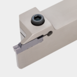
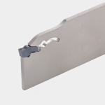
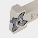
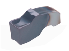
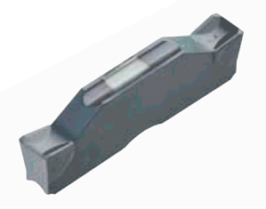
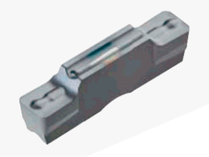
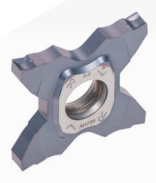
When selecting an outer diameter grooving tool, the preferred choice is a clamp-on type. The distinctive advantage of clamp-on grooving tools lies in their ability to perform both grooving and crossfeeding functions seamlessly with a single tool. Moreover, it is advisable to choose a tool based on specific machining requirements. Opt for a self-clamp type, ensuring superior chip control, particularly suitable for deep grooves. Alternatively, consider a screw clamp type when working with low workpiece rigidity, aligning the tool selection with the intended machining purpose for optimal performance.
Tungaloy´s recommendations:
Inserts can be categorized into two main types: pressed products, which undergo coating after the pressing process, and ground products, which are polished for enhanced precision. Polished inserts exhibit elevated processing accuracy, with selection contingent upon the specific precision requirements of the workpiece. Furthermore, the extent of workpiece protrusion and the chip’s groove width significantly influence machining accuracy. Extended overhang may lead to workpiece bending due to heightened cutting resistance. Conversely, acute groove widths or smaller corner radii can mitigate cutting resistance. Careful consideration of these factors is crucial for optimizing machining performance.
Typical width tolerance:
Pressed inserts: W ± 0.05 mm (.002″)
Ground inserts: W ± 0.025 mm (.001″)
Cross-feed machining with a grooving tool offers advantages such as reduced tool concentration and shorter machining times, particularly effective for shallow groove depths compared to the width. However, precision in tool usage and adherence to specific tool paths are crucial for optimal results. To ensure successful cross-feed machining, attention to the installation and cutting guide is paramount.
Minimizing resistance due to the clearance angle (α) during tool deflection facilitates effective cross-feed machining. Moreover, maintaining lateral feed stability necessitates a minimum depth of cut exceeding the chip corner R (rƐ), with the maximum depth of cut ideally set at approximately 80% of the groove width (W).
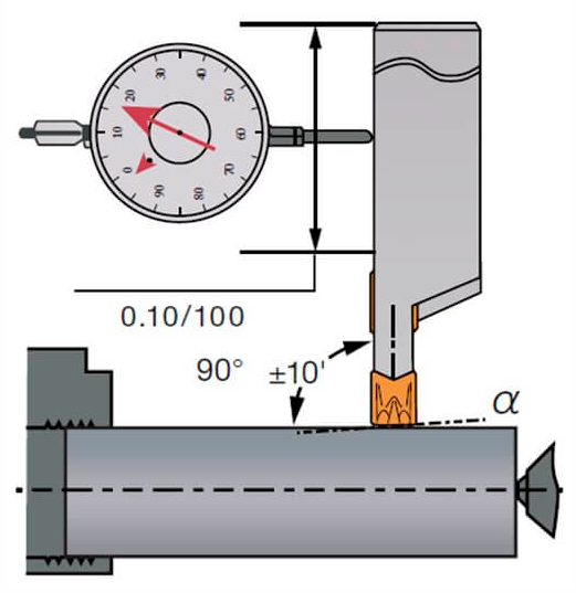
Notes on Tool Path (Grooving + Lateral Feed)
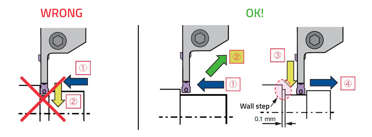
In cross-feed machining, potential cutting resistance poses a risk of tool breakage if deflection is not addressed. To mitigate this, ensure the tool is moved approximately 0.1 mm away from the workpiece near the wall before initiating the subsequent grooving operation. Additionally, if required, address any irregularities on the wall edges resulting from the initial punching process at the conclusion of the overall machining procedure.
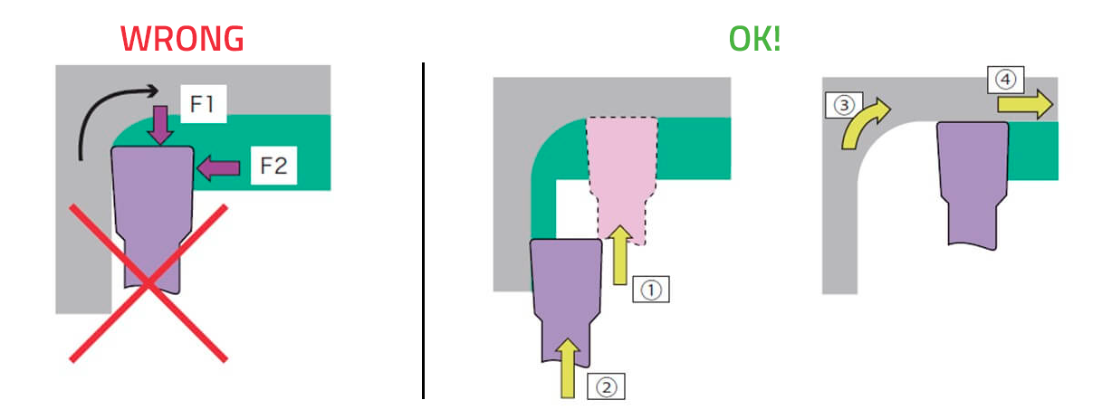
Notes on Tool Path (Corner R Machining)
Performing copying along the corner radius poses a risk of simultaneous force application from two directions, increasing the likelihood of tool breakage. To address this concern, employ a strategy of punching the side of the corner R and tracing along the wall edge. This approach effectively minimizes the force exerted simultaneously from two directions, reducing the risk of tool damage.
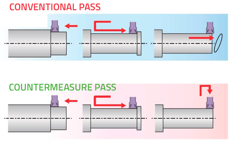
Notes on Tool Path (Ring Burr When Pulling Out)
When machining a rod-shaped workpiece with holes, the risk of ring burrs arises if the tool disengages during horizontal feed. This can lead to issues such as material damage or chip entanglement, especially if the ring burr becomes entwined with the tailstock. To prevent these complications, it is advisable to position the exit end below the groove width and punch out the remaining part, effectively averting the formation of ring burrs.
