

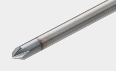
Foret en carbure monobloc revêtu pour une excellente stabilité |
 |
La géométrie de la nuance de forage idéales offrent des performances exceptionnelles dans une large gamme d’applications de forage.

Applications & Fonctionnalités
Applications

Fonctionnalités pour DSW
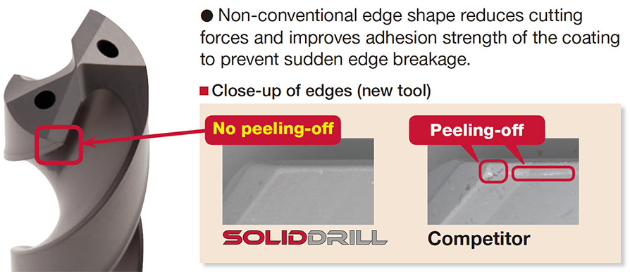
1. Nouvelle nuance revêtue avec une résistance à l’usure hautement améliorée
• Nouvelle nuance de carbure revêtu à haut niveau de polyvalence. Nuance parfaite pour une durée de vie stable et longue sur une large gamme de matériaux
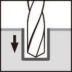
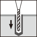
2. L’arête de coupe innovante offre un perçage fiable
• La forme non conventionnelle des arêtes réduit les forces de coupe et améliore la force d’adhérence du revêtement pour éviter la rupture soudaine des arêtes.
3. Style de tige standard mondial – Standardisé avec DIN6535-Form HA
• Seulement 6 diamètres de tige disponibles – ø6, ø8, ø10, ø12, ø14, ø16 mm. Cela réduit le nombre de pinces nécessaires.
Fonctionnalités pour DSM
1. Variété de dimensions et L/D
• Permet de percer des trous profonds jusqu’à 5 à 15 fois le diamètre du foret.
• Disponible en articles standard de ø0.1 to ø3.0 mm in 0.01 mm. Les diamètres de tige sont tous unifiés à ø3 mm.
2. Forets centraux pour l’usinage du trou de guidage
• Le type DSM-CP140 a un angle de pointe de 140° qui peut efficacement empêcher l’arête de coupe de s’écailler
• Le type DSM-CP90 type, qui a un angle de pointe de 90° peut également être utilisé pour le chanfreinage de l’embouchure du trou.
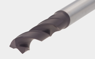
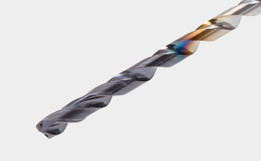
Corps d'outils & Nuances
Corps de foret
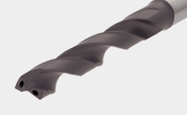
DSW-DI (ø3 – ø12 mm)
- Avec trou de liquide de refroidissement
DSW-DE (ø3 – ø12 mm)
- Sans trou de liquide de refroidissement. Type économique
DSW-CI (ø3 – ø10 mm)
- Cylindrical shank, with coolant holes
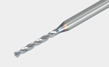
DSM (ø0.1 – ø3 mm)
- Petit diamètre. Foret carbure monobloc, L/D (ULDR) = 5 – 15
DSM-CP (ø3 mm)
- Forets pour trou central
Nuances principales
AH725
![]()
![]()
![]()
![]()
- P15 – P30 / M15 – M30 / K25 – K30 / S15 – S25
- Bel équilibre entre résistance à l’usure et à l’écaillage
- Convient pour l’usinage des aciers et des aciers inoxydables dans des conditions de coupe générale
YH170
![]()
![]()
- P20 – P35 / M20 – M35
- Haute résistance à l’usure et à la rupture
- Conçu pour percer les aciers au carbone et les aciers inoxydables
YH180
![]()
![]()
- High wear resistance
- Designed for drilling carbon steel and stainless steel
Exemples pratiques
Exemple #1
Ingénierie générale
| Partie: | Parties machine |
| Matériau: | C55 (ISO) |
| Corps de foret: | DSW103-040-12DE3 |
| Diamètre du trou: | øDc = 10.3 (mm) |
| Nuance: | AH725 |
| Conditions de coupe: | Vc = 50 (m/min) f = 0.3 (mm/rev) H = 24 (mm) Liquide de refroidissement : avec (externe) Machine: Horizontal MC |

Conditions de coupe standards
DSW-DE (External supply)
| ISO | Workpiece material | Brinell hardness (HB) |
Cutting speedVc (m/min) | Feed: f (mm/rev) | ||||
|---|---|---|---|---|---|---|---|---|
| ø3 – ø6 | ø6 – ø10 | ø10 – ø16 | ø3 – ø6 | ø6 – ø10 | ø10 – ø12 | |||
 |
Low carbon steels (C < 0.3) SS400, SM490, S25C, etc. C15E4, E275A, E355D, etc. |
– 180 | 40 – 100 | 60 – 120 | 60 – 130 | 0.15 – 0.3 | 0.15 – 0.35 | 0.2 – 0.5 |
| Carbon steels (C > 0.3) S45C, S55C, , etc. C45, C55, etc. |
180 – 300 | 40 – 90 | 50 – 120 | 60 – 130 | 0.15 – 0.3 | 0.15 – 0.35 | 0.2 – 0.4 | |
| High alloy steels SCM440, etc. 42CrMo4, etc. |
250 – 350 | 40 – 80 | 50 – 100 | 50 – 100 | 0.1 – 0.2 | 0.15 – 0.3 | 0.15 – 0.35 | |
 |
Stainless steels SUS304, etc. X5CrNi18-9, etc. |
– 200 | 20 – 40 | 30 – 50 | 30 – 60 | 0.05 – 0.2 | 0.1 – 0.25 | 0.1 – 0.3 |
 |
Grey cast irons FC300, etc. 250, etc. |
– 200 | 40 – 90 | 50 – 95 | 50 – 100 | 0.15 – 0.3 | 0.2 – 0.4 | 0.2 – 0.5 |
| Ductile cast irons FCD450, etc. 450-10S, etc. |
– 300 | 30 – 80 | 40 – 90 | 45 – 90 | 0.1 – 0.3 | 0.2 – 0.4 | 0.2 – 0.4 | |
 |
Aluminium alloys ADC12, etc. AlSi11Cu3, etc. |
– | 40 – 90 | 50 – 100 | 50 – 100 | 0.15 – 0.3 | 0.2 – 0.4 | 0.2 – 0.5 |
 |
Titanium alloys Ti-6Al-4V, etc. |
– | 20 – 40 | 20 – 40 | 20 – 40 | 0.1 – 0.2 | 0.15 – 0.25 | 0.15 – 0.4 |
| Heat-resistant alloys, Inconel Inconel 718, etc. |
250 – | 10 – 30 | 10 – 30 | 10 – 30 | 0.03 – 0.07 | 0.05 – 0.1 | 0.07 – 0.12 | |
 |
High hardened steels SKD11, etc. X153CrMoV12, etc. |
– 40HRC | 20 – 40 | 20 – 40 | 20 – 40 | 0.05 – 0.15 | 0.05 – 0.15 | 0.05 – 0.2 |
- The cutting parameters shown in the table are merely a starting guideline for general machining. Values should be varied depending on the power or rigidity of the machine to be used. Optimum conditions should be selected depending on the actual chip control or damage on edges.
- When using the smaller diameter tools in each range, set the feed “f” to the lower recommended values.
- The coolant supply is critical for the provision of stable machining conditions and enhanced tool life. A large coolant volume should be supplied, especially when drilling difficult-to-cut materials.
- When drilling stainless steel with low machinability such as austenitic stainless steel with a depth deeper than L/D = 3, a pecking cycle or internal coolant supply is recommended.
DSW-DI (Internal supply)
| ISO | Workpiece material | Brinell hardness (HB) |
Cutting speedVc (m/min) | Feed: f (mm/rev) | ||||
|---|---|---|---|---|---|---|---|---|
| ø3 – ø6 | ø6 – ø10 | ø10 – ø16 | ø3 – ø6 | ø6 – ø10 | ø10 – ø12 | |||
|
Low carbon steels (C < 0.3) SS400, SM490, S25C, etc. C15E4, E275A, E355D, etc. |
– 180 | 70 – 140 | 80 – 160 | 90 – 190 | 0.15 – 0.3 | 0.15 – 0.35 | 0.2 – 0.5 |
| Carbon steels (C > 0.3) S45C, S55C, , etc. C45, C55, etc. |
180 – 300 | 50 – 130 | 70 – 160 | 80 – 170 | 0.15 – 0.3 | 0.15 – 0.35 | 0.2 – 0.4 | |
| High alloy steels SCM440, etc. 42CrMo4, etc. |
250 – 350 | 40 – 100 | 60 – 140 | 60 – 160 | 0.1 – 0.2 | 0.15 – 0.3 | 0.15 – 0.35 | |
|
Stainless steels SUS304, etc. X5CrNi18-9, etc. |
– 200 | 25 – 75 | 50 – 100 | 50 – 120 | 0.05 – 0.2 | 0.1 – 0.25 | 0.1 – 0.3 |
|
Grey cast irons FC300, etc. 250, etc. |
– 200 | 80 – 140 | 100 – 160 | 100 – 180 | 0.15 – 0.3 | 0.2 – 0.4 | 0.2 – 0.45 |
| Ductile cast irons FCD450, etc. 450-10S, etc. |
– 300 | 70 – 140 | 80 – 150 | 80 – 170 | 0.1 – 0.3 | 0.2 – 0.4 | 0.2 – 0.45 | |
|
Aluminium alloys ADC12, etc. AlSi11Cu3, etc. |
– | 60 – 200 | 60 – 200 | 60 – 200 | 0.15 – 0.3 | 0.2 – 0.4 | 0.2 – 0.5 |
|
Titanium alloys Ti-6Al-4V, etc. |
– | 20 – 60 | 30 – 80 | 30 – 80 | 0.1 – 0.2 | 0.1 – 0.25 | 0.15 – 0.4 |
| Heat-resistant alloys, Inconel Inconel 718, etc. |
250 – | 10 – 30 | 10 – 40 | 10 – 40 | 0.03 – 0.07 | 0.05 – 0.1 | 0.07 – 0.15 | |
|
High hardened steels SKD11, etc. X153CrMoV12, etc. |
– 40HRC | 20 – 50 | 30 – 60 | 30 – 60 | 0.05 – 0.15 | 0.05 – 0.15 | 0.05 – 0.2 |
- The cutting parameters shown in the table are merely a starting guideline for general machining. Values should be varied depending on the power or rigidity of the machine to be used. Optimum conditions should be selected depending on the actual chip control or damage on edges.
- When using the smaller diameter tools in each range, set the feed “f” to the lower recommended values.
- Oil holes that become blocked may cause drill breakages. A fi lter to prevent the circulation of chips must be used on the coolant supply system.
DSW-CI (16xD, 20xD)
| ISO | Workpiece material | Cutting speed Vc (m/min) |
Feed: f (mm/rev) | ||
|---|---|---|---|---|---|
| Tool diameter: DC (mm) | |||||
| ø3 – ø5 | ø5.1 – ø8 | ø8.1 – ø10 | |||
|
Low carbon steels (C < 0.3) SS400, SM490, S25C, etc. C15E4, E275A, E355D, etc. |
70 – 90 | 0.1 – 0.18 | 0.1 – 0.2 | 0.1 – 0.25 |
| High carbon steels (C > 0.3) S45C, S55C, etc. C45, C55, etc. |
70 – 90 | 0.1 – 0.18 | 0.1 – 0.2 | 0.1 – 0.25 | |
| Low alloy steels SCM415, etc. 18CrMo4, etc. |
70 – 90 | 0.1 – 0.18 | 0.1 – 0.2 | 0.1 – 0.25 | |
| Alloy steels SCM440, SCr420, etc. 42CrMo4, 20Cr4, etc. |
75 – 85 | 0.08 – 0.14 | 0.08 – 0.18 | 0.12 – 0.2 | |
|
Stainless steels SUS304, SUS316, etc. X5CrNi18-9, X5CrNiMo17-12-2, etc. |
55 – 65 | 0.04 – 0.12 | 0.08 – 0.16 | 0.1 – 0.18 |
|
Grey cast irons FC250, etc. GG25, etc. |
80 – 100 | 0.14 – 0.24 | 0.16 – 0.26 | 0.18 – 0.3 |
| Ductile cast irons FCD700, etc. GGG70, etc. |
80 – 100 | 0.14 – 0.24 | 0.16 – 0.26 | 0.18 – 0.3 | |
|
Titanium alloys Ti-6Al-4V, etc. |
35 – 45 | 0.06 – 0.12 | 0.08 – 0.16 | 0.1 – 0.18 |
| Nickel-based alloys | 30 – 40 | 0.06 – 0.12 | 0.08 – 0.16 | 0.1 – 0.18 | |
DSW-CI (30xD)
| ISO | Workpiece material | Cutting speed Vc (m/min) |
Feed: f (mm/rev) | ||
|---|---|---|---|---|---|
| Tool diameter: DC (mm) | |||||
| ø3 – ø5 | ø5.1 – ø8 | ø8.1 – ø10 | |||
|
Low carbon steels (C < 0.3) SS400, SM490, S25C, etc. C15E4, E275A, E355D, etc. |
70 – 90 | 0.08 – 0.11 | 0.12 – 0.17 | 0.1 – 0.22 |
| High carbon steels (C > 0.3) S45C, S55C, etc. C45, C55, etc. |
70 – 90 | 0.08 – 0.11 | 0.12 – 0.17 | 0.1 – 0.22 | |
| Low alloy steels SCM415, etc. 18CrMo4, etc. |
70 – 90 | 0.08 – 0.11 | 0.12 – 0.17 | 0.1 – 0.22 | |
| Alloy steels SCM440, SCr420, etc. 42CrMo4, 20Cr4, etc. |
75 – 85 | 0.06 – 0.09 | 0.08 – 0.14 | 0.1 – 0.18 | |
|
Stainless steels SUS304, SUS316, etc. X5CrNi18-9, X5CrNiMo17-12-2, etc. |
55 – 65 | 0.04 – 0.1 | 0.08 – 0.14 | 0.1 – 0.16 |
|
Grey cast irons FC250, etc. GG25, etc. |
80 – 100 | 0.14 – 0.22 | 0.16 – 0.26 | 0.18 – 0.25 |
| Ductile cast irons FCD700, etc. GGG70, etc. |
80 – 100 | 0.14 – 0.22 | 0.16 – 0.24 | 0.18 – 0.25 | |
|
Titanium alloys Ti-6Al-4V, etc. |
35 – 45 | 0.06 – 0.1 | 0.08 – 0.12 | 0.1 – 0.13 |
| Nickel-based alloys | 30 – 40 | 0.06 – 0.1 | 0.08 – 0.12 | 0.08 – 0.13 | |
DSM
| ISO | Workpiece material | Hardness | Cutting speedVc (m/min) | Feed: f (mm/rev) | ||||||
|---|---|---|---|---|---|---|---|---|---|---|
| ø0.1 – ø0.3 | ø0.31 – ø0.5 | ø0.51 – ø3 | ø0.1 – ø0.3 | ø0.31 – ø0.5 | ø0.51 – ø1 | ø1.01 – ø2 | ø2.01 – ø3 | |||
|
Carbon steels, Alloy steels |
– 300HB | 5 – 20 | 15 – 30 | 25 – 60 | 0.001 – 0.004 | 0.002 – 0.01 | 0.005 – 0.05 | 0.03 – 0.09 | 0.05 – 0.1 |
|
Stainless steels | – 200HB | 2 – 12 | 6 – 18 | 10 – 20 | 0.0005 – 0.004 | 0.002 – 0.008 | 0.005 – 0.03 | 0.01 – 0.04 | 0.02 – 0.05 |
|
Grey cast irons | 150 – 250HB | 5 – 15 | 10 – 25 | 20 – 50 | 0.0005 – 0.004 | 0.002 – 0.012 | 0.005 – 0.03 | 0.01 – 0.06 | 0.03 – 0.12 |
| Ductile cast irons | 150 – 250HB | 5 – 15 | 10 – 25 | 20 – 50 | 0.001 – 0.003 | 0.002 – 0.01 | 0.005 – 0.02 | 0.01 – 0.05 | 0.03 – 0.1 | |
|
Aluminium alloys | – | 10 – 20 | 10 – 30 | 20 – 50 | 0.001 – 0.01 | 0.005 – 0.03 | 0.01 – 0.05 | 0.04 – 0.15 | 0.06 – 0.2 |
| Copper / Brass | – | 10 – 20 | 10 – 30 | 20 – 50 | 0.001 – 0.01 | 0.005 – 0.03 | 0.01 – 0.05 | 0.04 – 0.15 | 0.06 – 0.2 | |
|
Heat-resistant alloys | – 40HRC | 2 – 6 | 5 – 10 | 8 – 20 | 0.0005 – 0.003 | 0.002 – 0.004 | 0.002 – 0.004 | 0.002 – 0.004 | ※ |
|
High hardened steels | – 50HRC | 4 – 8 | 6 – 10 | 6 – 16 | 0.0005 – 0.002 | 0.001 – 0.005 | 0.005 – 0.02 | 0.01 – 0.03 | 0.02 – 0.06 |
※ Not recommended
- When the drilling depth is deeper than L/D = 5, use drill pecking every 10 to 50% of the drill diameter.
- The above cutting conditions are applied to when a water soluble cutting fluid is used. For drilling a hole smaller than ø0. 3 mm, use of a starting drill is recommended.
- When setting the drill, the drill runout should be within 0.002 mm on the taper. (Especially for the drill diameter smaller than ø0.5 mm)
DSM-CP
| ISO | Workpiece material | Hardness | Cutting speedVc (m/min) | Feed: f (mm/rev) | |
|---|---|---|---|---|---|
| DSM-CP90 | DSM-CP140 | ||||
|
Carbon, Mild and Alloy steels | – 300HB | 30 – 80 | 0.01 – 0.06 | 0.03 – 0.08 |
|
Stainless steels | – 200HB | 15 – 40 | 0.01 – 0.03 | 0.02 – 0.06 |
|
Grey and ductile cast irons | 150 – 250HB | 30 – 80 | 0.02 – 0.06 | 0.05 – 0.1 |
|
Aluminium alloys | – | 60 – 120 | 0.02 – 0.1 | 0.05 – 0.15 |
|
High hardened steels | – 45HRC | 10 – 40 | ※ | 0.01 – 0.05 |
※ Not recommended
- Use DSM-CP140 for drilling hard materials and stainless steel that have work-hardening characteristic.
- The above cutting conditions are designed when using water-soluble cutting fluid, in which case, set the cutting speed to the lower side of the range.
Pour plus d’informations sur ce produit, visitez notre e-catalogue en ligne ou téléchargez le rapport produit :
e-Catalog

Industries |
|
Industries Learn more |

e-Catalog |
|
e-Catalog Learn more |
Ressources
 Tungaloy APP
 TUNG NaviConditions De Coupe Recommandées
 Machine Power Calculator
 Turning Insert Selection Guide
 Études de CasExplorez les études de cas de Tungaloy et découvrez de nombreuses informations techniques vérifiées
 Guides techniquesAccédez aux guides techniques de Tungaloy pour des informations, des références et des ressources précieuses.
 MatrixSystème De Gestion D'outils