

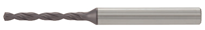
性能稳定的涂层整体硬质合金钻头
钻头几何形状和合金成分的理想组合,在各种钻孔加工中性能出色

应用 & 特点
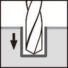
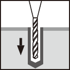
应用

DSW 特点
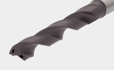
1. 高耐磨性的新型涂层材质
• 新的涂层硬质合金材质具有高通用性。是用于各种材料加工获得长而稳定刀具寿命的完美材质。
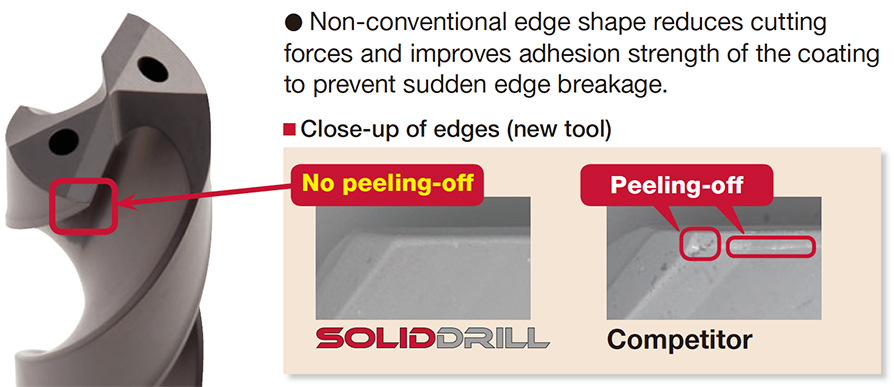
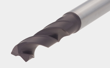
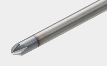
2. 创新的刃口实现可靠的钻孔加工
• 非传统的刃口形状减少了切削力并且提高了涂层粘着强度,防止突发的刃口断裂。
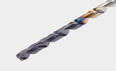
3. 全球标准柄类型- DIN6535-Form HA 标准
• 仅有6种柄部直径尺寸可选-ø6, ø8, ø10, ø12, ø14, ø16 mm。这样降低了所需筒夹的种类。
DSM 特点
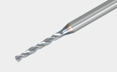
1. 各种尺寸和 L/D
• 允许深孔钻孔深度达5到15倍钻头直径。
• 从ø0.1 到 ø3.0mm直径范围内以0.01mm递增均为标准品。柄部直径均统一为ø3 mm。
2. 引导孔加工用中心钻
• DSM-CP140 型,拥有140°钻尖角,可以有效防止刃口崩刃。
• DSM-CP90 型,拥有 90°钻尖角,可以用于孔口倒角。
钻体 & 材质
钻体
主要材质
实际案例
案例 #1
通用工程
| 零件: | 机床零件 |
| 材料: | C55 (ISO) |
| 钻体: | DSW103-040-12DE3 |
| 孔直径: | øDc = 10.3 (mm) |
| 材质: | AH725 |
| 加工条件: | Vc = 50 (m/min) f = 0.3 (mm/rev) H = 24 (mm) 冷却方式: 冷却液(外冷) 机床: 卧式加工中心 |

标准加工条件
DSW-DE (外冷)
| ISO | 工件材料 | 布氏硬度 (HB) |
切削速度Vc (m/min) | 进给: f (mm/rev) | ||||
|---|---|---|---|---|---|---|---|---|
| ø3 – ø6 | ø6 – ø10 | ø10 – ø16 | ø3 – ø6 | ø6 – ø10 | ø10 – ø12 | |||
 |
低碳钢(C < 0.3) SS400、SM490、S25C 等 C15E4、E275A、E355D 等 |
– 180 | 40 – 100 | 60 – 120 | 60 – 130 | 0.15 – 0.3 | 0.15 – 0.35 | 0.2 – 0.5 |
| 碳钢(C > 0.3) S45C、S55C 等 C45、C55 等 |
180 – 300 | 40 – 90 | 50 – 120 | 60 – 130 | 0.15 – 0.3 | 0.15 – 0.35 | 0.2 – 0.4 | |
| 高合金钢 SCM440 等 42CrMo4 等 |
250 – 350 | 40 – 80 | 50 – 100 | 50 – 100 | 0.1 – 0.2 | 0.15 – 0.3 | 0.15 – 0.35 | |
 |
不锈钢 SUS304 等 X5CrNi18-9 等 |
– 200 | 20 – 40 | 30 – 50 | 30 – 60 | 0.05 – 0.2 | 0.1 – 0.25 | 0.1 – 0.3 |
 |
灰铸铁 FC300 等 250 等 |
– 200 | 40 – 90 | 50 – 95 | 50 – 100 | 0.15 – 0.3 | 0.2 – 0.4 | 0.2 – 0.5 |
| 球墨铸铁 FCD450 等 450-10S 等 |
– 300 | 30 – 80 | 40 – 90 | 45 – 90 | 0.1 – 0.3 | 0.2 – 0.4 | 0.2 – 0.4 | |
 |
铝合金 ADC12 等 AlSi11Cu3 等 |
– | 40 – 90 | 50 – 100 | 50 – 100 | 0.15 – 0.3 | 0.2 – 0.4 | 0.2 – 0.5 |
 |
钛合金 Ti-6Al-4V 等 |
– | 20 – 40 | 20 – 40 | 20 – 40 | 0.1 – 0.2 | 0.15 – 0.25 | 0.15 – 0.4 |
| 耐热合金,铬镍铁合金 铬镍铁合金 718 等 |
250 – | 10 – 30 | 10 – 30 | 10 – 30 | 0.03 – 0.07 | 0.05 – 0.1 | 0.07 – 0.12 | |
 |
高硬度钢 SKD11 等 X153CrMoV12 等 |
– 40HRC | 20 – 40 | 20 – 40 | 20 – 40 | 0.05 – 0.15 | 0.05 – 0.15 | 0.05 – 0.2 |
- 表中所示的切削参数只是一般加工的起始指南。应根据所用机床的功率或刚性改变参数值。应根据实际切屑控制或刀刃磨损情况选择最佳条件。
- 使用每个范围内直径较小的刀具时,将进给 “f “设置为较低的推荐值。
- 冷却液供应对于提供稳定的加工条件和延长刀具寿命至关重要。尤其是在钻削难以切削的材料时,应提供较大的冷却液量。
- 在钻孔深度大于 L/D = 3 的奥氏体不锈钢等可加工性较低的不锈钢时,建议采用啄孔循环或内部冷却液供给方式。
DSW-DI (内冷)
| ISO | 工件材料 | 布氏硬度 (HB) |
切削速度Vc (m/min) | 进给: f (mm/rev) | ||||
|---|---|---|---|---|---|---|---|---|
| ø3 – ø6 | ø6 – ø10 | ø10 – ø16 | ø3 – ø6 | ø6 – ø10 | ø10 – ø12 | |||
|
低碳钢(C < 0.3) SS400、SM490、S25C 等 C15E4、E275A、E355D 等 |
– 180 | 70 – 140 | 80 – 160 | 90 – 190 | 0.15 – 0.3 | 0.15 – 0.35 | 0.2 – 0.5 |
| 碳钢(C > 0.3) S45C、S55C 等 C45、C55 等 |
180 – 300 | 50 – 130 | 70 – 160 | 80 – 170 | 0.15 – 0.3 | 0.15 – 0.35 | 0.2 – 0.4 | |
| 高合金钢 SCM440 等 42CrMo4 等 |
250 – 350 | 40 – 100 | 60 – 140 | 60 – 160 | 0.1 – 0.2 | 0.15 – 0.3 | 0.15 – 0.35 | |
|
不锈钢 SUS304 等 X5CrNi18-9 等 |
– 200 | 25 – 75 | 50 – 100 | 50 – 120 | 0.05 – 0.2 | 0.1 – 0.25 | 0.1 – 0.3 |
|
灰铸铁 FC300 等 250 等 |
– 200 | 80 – 140 | 100 – 160 | 100 – 180 | 0.15 – 0.3 | 0.2 – 0.4 | 0.2 – 0.45 |
| 球墨铸铁 FCD450 等 450-10S 等 |
– 300 | 70 – 140 | 80 – 150 | 80 – 170 | 0.1 – 0.3 | 0.2 – 0.4 | 0.2 – 0.45 | |
|
铝合金 ADC12 等 AlSi11Cu3 等 |
– | 60 – 200 | 60 – 200 | 60 – 200 | 0.15 – 0.3 | 0.2 – 0.4 | 0.2 – 0.5 |
|
钛合金 Ti-6Al-4V 等 |
– | 20 – 60 | 30 – 80 | 30 – 80 | 0.1 – 0.2 | 0.1 – 0.25 | 0.15 – 0.4 |
| 耐热合金,铬镍铁合金 铬镍铁合金 718 等 |
250 – | 10 – 30 | 10 – 40 | 10 – 40 | 0.03 – 0.07 | 0.05 – 0.1 | 0.07 – 0.15 | |
|
高硬度钢 SKD11 等 X153CrMoV12 等 |
– 40HRC | 20 – 50 | 30 – 60 | 30 – 60 | 0.05 – 0.15 | 0.05 – 0.15 | 0.05 – 0.2 |
- 表中所示的切削参数只是一般加工的起始指南。应根据所用机床的功率或刚性改变参数值。应根据实际切屑控制或边缘损坏情况选择最佳条件。
- 使用每个范围内直径较小的刀具时,将进给 “f “设置为较低的推荐值。
- 冷却孔堵塞可能导致钻头断裂。必须在冷却液供应系统上安装防止切屑循环的过滤器。
DSW-CI (16xD, 20xD)
| ISO | 工件材料 | 切削速度 Vc (m/min) |
进给: f (mm/rev) | ||
|---|---|---|---|---|---|
| 刀具直径: DC (mm) | |||||
| ø3 – ø5 | ø5.1 – ø8 | ø8.1 – ø10 | |||
|
低碳钢(C < 0.3) SS400、SM490、S25C 等 C15E4、E275A、E355D 等 |
70 – 90 | 0.1 – 0.18 | 0.1 – 0.2 | 0.1 – 0.25 |
| 高碳钢(C > 0.3) S45C、S55C 等 C45、C55 等 |
70 – 90 | 0.1 – 0.18 | 0.1 – 0.2 | 0.1 – 0.25 | |
| 低合金钢 SCM415 等 18CrMo4 等 |
70 – 90 | 0.1 – 0.18 | 0.1 – 0.2 | 0.1 – 0.25 | |
| 合金钢 SCM440、SCr420 等 42CrMo4, 20Cr4 等 |
75 – 85 | 0.08 – 0.14 | 0.08 – 0.18 | 0.12 – 0.2 | |
|
不锈钢 SUS304、SUS316 等 X5CrNi18-9、 X5CrNiMo17-12-2 等 |
55 – 65 | 0.04 – 0.12 | 0.08 – 0.16 | 0.1 – 0.18 |
|
灰铸铁 FC250 等 GG25 等 |
80 – 100 | 0.14 – 0.24 | 0.16 – 0.26 | 0.18 – 0.3 |
| 球墨铸铁 FCD700 等 GGG70 等 |
80 – 100 | 0.14 – 0.24 | 0.16 – 0.26 | 0.18 – 0.3 | |
|
钛合金 Ti-6Al-4V 等 |
35 – 45 | 0.06 – 0.12 | 0.08 – 0.16 | 0.1 – 0.18 |
| 镍基合金 | 30 – 40 | 0.06 – 0.12 | 0.08 – 0.16 | 0.1 – 0.18 | |
DSW-CI (30xD)
| ISO | 工件材料 | 切削速度 Vc (m/min) |
进给: f (mm/rev) | ||
|---|---|---|---|---|---|
| 刀具直径: DC (mm) | |||||
| ø3 – ø5 | ø5.1 – ø8 | ø8.1 – ø10 | |||
|
低碳钢(C < 0.3) SS400、SM490、S25C 等 C15E4、E275A、E355D 等 |
70 – 90 | 0.08 – 0.11 | 0.12 – 0.17 | 0.1 – 0.22 |
| 高碳钢(C > 0.3) S45C、S55C 等 C45、C55 等 |
70 – 90 | 0.08 – 0.11 | 0.12 – 0.17 | 0.1 – 0.22 | |
| 低合金钢 SCM415 等 18CrMo4 等 |
70 – 90 | 0.08 – 0.11 | 0.12 – 0.17 | 0.1 – 0.22 | |
| 合金钢 SCM440、SCr420 等 42CrMo4, 20Cr4 等 |
75 – 85 | 0.06 – 0.09 | 0.08 – 0.14 | 0.1 – 0.18 | |
|
不锈钢 SUS304、SUS316 等 X5CrNi18-9、 X5CrNiMo17-12-2 等 |
55 – 65 | 0.04 – 0.1 | 0.08 – 0.14 | 0.1 – 0.16 |
|
灰铸铁 FC250 等 GG25 等 |
80 – 100 | 0.14 – 0.22 | 0.16 – 0.26 | 0.18 – 0.25 |
| 球墨铸铁 FCD700 等 GGG70 等 |
80 – 100 | 0.14 – 0.22 | 0.16 – 0.24 | 0.18 – 0.25 | |
|
钛合金 Ti-6Al-4V 等 |
35 – 45 | 0.06 – 0.1 | 0.08 – 0.12 | 0.1 – 0.13 |
| 镍基合金 | 30 – 40 | 0.06 – 0.1 | 0.08 – 0.12 | 0.08 – 0.13 | |
DSM
| ISO | 工件材料 | 硬度 | 切削速度 Vc (m/min) | 进给: f (mm/rev) | ||||||
|---|---|---|---|---|---|---|---|---|---|---|
| ø0.1 – ø0.3 | ø0.31 – ø0.5 | ø0.51 – ø3 | ø0.1 – ø0.3 | ø0.31 – ø0.5 | ø0.51 – ø1 | ø1.01 – ø2 | ø2.01 – ø3 | |||
|
碳钢 合金钢 |
– 300HB | 5 – 20 | 15 – 30 | 25 – 60 | 0.001 – 0.004 | 0.002 – 0.01 | 0.005 – 0.05 | 0.03 – 0.09 | 0.05 – 0.1 |
|
不锈钢 | – 200HB | 2 – 12 | 6 – 18 | 10 – 20 | 0.0005 – 0.004 | 0.002 – 0.008 | 0.005 – 0.03 | 0.01 – 0.04 | 0.02 – 0.05 |
|
灰铸铁 | 150 – 250HB | 5 – 15 | 10 – 25 | 20 – 50 | 0.0005 – 0.004 | 0.002 – 0.012 | 0.005 – 0.03 | 0.01 – 0.06 | 0.03 – 0.12 |
| 球墨铸铁 | 150 – 250HB | 5 – 15 | 10 – 25 | 20 – 50 | 0.001 – 0.003 | 0.002 – 0.01 | 0.005 – 0.02 | 0.01 – 0.05 | 0.03 – 0.1 | |
|
铝合金 | – | 10 – 20 | 10 – 30 | 20 – 50 | 0.001 – 0.01 | 0.005 – 0.03 | 0.01 – 0.05 | 0.04 – 0.15 | 0.06 – 0.2 |
| 铜/黄铜 | – | 10 – 20 | 10 – 30 | 20 – 50 | 0.001 – 0.01 | 0.005 – 0.03 | 0.01 – 0.05 | 0.04 – 0.15 | 0.06 – 0.2 | |
|
耐热合金 | – 40HRC | 2 – 6 | 5 – 10 | 8 – 20 | 0.0005 – 0.003 | 0.002 – 0.004 | 0.002 – 0.004 | 0.002 – 0.004 | ※ |
|
高硬度钢 | – 50HRC | 4 – 8 | 6 – 10 | 6 – 16 | 0.0005 – 0.002 | 0.001 – 0.005 | 0.005 – 0.02 | 0.01 – 0.03 | 0.02 – 0.06 |
※ 不推荐
- 当钻孔深度大于 L/D = 5 时,每隔钻孔直径的 10%至 50%使用啄钻。
- 上述切削条件适用于使用水溶性切削液时。钻孔小于 ø0. 3 mm的孔时,建议使用起钻。
- 调试钻头时,锥度跳动应在 0.002 mm以内(尤其是钻头直径小于 ø0.5 mm时)。(特别是钻头直径小于 ø0.5 mm 时)。
DSM-CP
| ISO | 工件材料 | 硬度 | 切削速度Vc (m/min) | 进给: f (mm/rev) | |
|---|---|---|---|---|---|
| DSM-CP90 | DSM-CP140 | ||||
|
碳钢、低碳钢和合金钢 | – 300HB | 30 – 80 | 0.01 – 0.06 | 0.03 – 0.08 |
|
不锈钢 | – 200HB | 15 – 40 | 0.01 – 0.03 | 0.02 – 0.06 |
|
灰口铸铁和球墨铸铁 | 150 – 250HB | 30 – 80 | 0.02 – 0.06 | 0.05 – 0.1 |
|
铝合金 | – | 60 – 120 | 0.02 – 0.1 | 0.05 – 0.15 |
|
高硬度钢 | – 45HRC | 10 – 40 | ※ | 0.01 – 0.05 |
※ 不推荐
- 使用 DSM-CP140 可钻硬质材料和具有加工硬化特性的不锈钢。
- 上述切削条件是在使用水溶性切削液时设计的,在这种情况下,请将切削速度设为范围的下限。
关于该产品的更多信息,请访问我们的线上e-catalog或者下载产品样本:
e-Catalog
SolidDrill
GigaMiniDrill


相关资料
 Tungaloy APP
 TUNG Navi满足您特殊要求的刀具建议
 机床功率计算器
 车刀片选择指南
 泰珂洛成功报告(TSR)只需简单搜索,即可获取最佳加工案例, 获得改进启发。
 技术指南访问泰珂洛的技术指南,获取有价值的见解、参考资料和资源。
 Matrix刀具管理系统