
Slot Mills as a Machining Option ─ Expanding the Possibilities with One Tool, from Deep Grooving, Side Walls, and Cut-off to Interference Avoidance
Slot mills are often regarded as “old-fashioned tools dedicated to cut-off and grooving.”
In reality, however, they are highly versatile and productive tools capable of covering areas that are difficult to reach with end mills, including deep grooves, side-wall accuracy, thin slots, keyways, parallel two-face machining, and interference avoidance.
They have many cutting edges around the circumference, make it easier to minimize overhang, and allow the use of a favorable tool diameter relative to the groove width. By taking advantage of these characteristics, machining operations that were previously abandoned due to chatter, wall deflection, or chip clogging can be transformed into stable mass-production processes.
This article explains the basics of slot mills, where they are effective, and how to select them. It also goes deeper into condition setting to bring out their performance, especially the often-overlooked concept of chip thickness.
What You Will Learn in This Article
- What is a slot mill? Differences from end mills
- Why slot mills are effective for deep grooves, side walls, and cut-off operations
- Types of slot mills and their suitable applications
- End mills vs. slot mills: key criteria for proper tool selection
- Basic tips for stable machining
- Understanding chip thickness when ae/DC is small
- Common problems and points to review
- Special form cutters as an option
- Summary
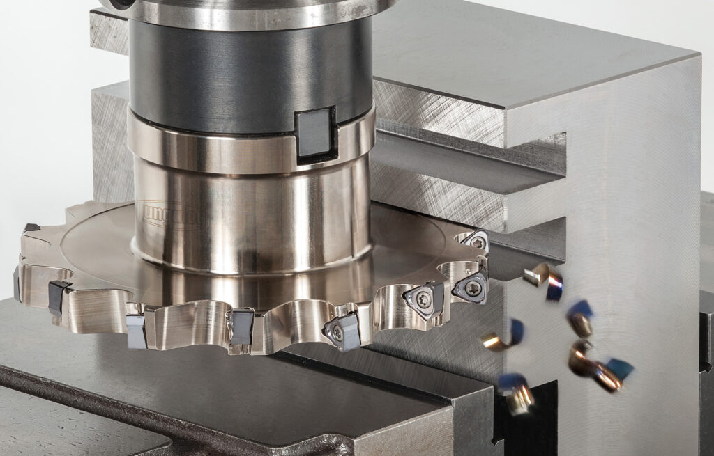
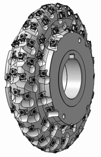
1. What is a slot mill? ─ A tool that cuts with the “peripheral side edges”
Slot mills are a group of tools that use cutting edges on the side of the tool periphery to machine grooves, shoulders, and faces. They are used for deep and narrow grooves, applications requiring side-wall accuracy, cut-off, keyways, and parallel two-face machining.
A common misconception is that they are “old-fashioned tools dedicated to cut-off and grooving.” In actual machining, they are also effective for shoulder milling and face milling where interference avoidance is required. With the growing adoption of 5-axis machining, their value is being rediscovered as tools that can approach the workpiece from the side with a short tool length.
Differences from Similar Tools
| Tool | Main Strengths | Difference from Slot Mills |
|---|---|---|
| Face mill | Face milling | Not suitable as a substitute for side-wall machining |
| End mill | General-purpose machining | In deep grooves, overhang becomes long, making deflection and chatter more likely |
| Slitting saw | Cut-off and thin grooving | A thin-blade version of a slot mill |
2. Typical Applications Where Slot Mills Are Effective
Narrow width relative to depth
With end mills, tool overhang becomes longer, making deflection, chatter, and dimensional error more likely. Slot mills are often advantageous because even when the tool is thin relative to its diameter, arbor support and disc rigidity provide stability.
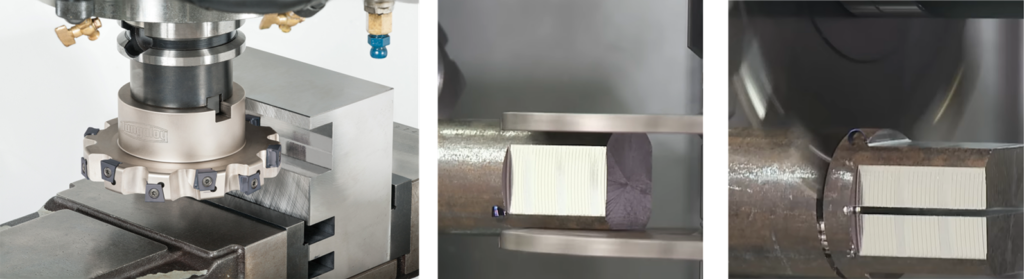
When right-angle accuracy and parallelism of side walls are required
Slot milling is highly effective for forming side-wall shapes. In gang milling, two cutters and spacers may allow two parallel faces to be machined in a single pass.
When reducing wasted material in cut-off and thin-slot machining
Thin-blade tools have a small cutting allowance, helping to reduce material loss. Even in deep and narrow grooves, high efficiency can be achieved when the tool geometry and chip evacuation are properly matched.
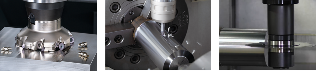
Interference avoidance and accessibility in 5-axis machining
Slot mills can enter thinly from the side in areas where large face mills are difficult to apply from the front or where long end mills do not provide sufficient clearance. In 5-axis machining centers, the increased freedom of the tool axis makes slot mills an even more valuable option.
POINT
An option for avoiding interference while securing rigidity
Slot mills are not “tools only for grooving.” They are an option that improves machining feasibility in deep grooves, side-wall machining, cut-off operations, and side-approach machining.
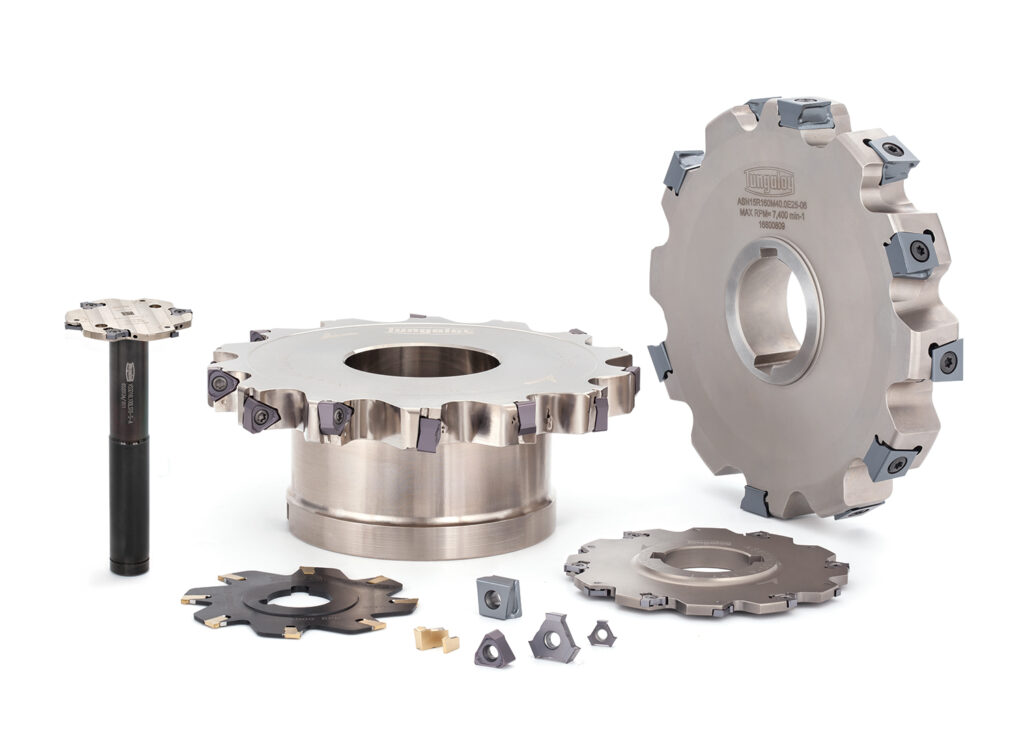
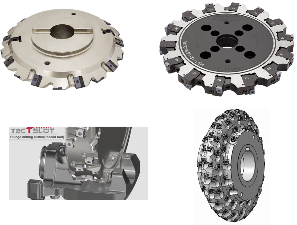
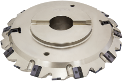
3. Basic Classification of Slot Mills ─ Which Type Should You Choose?
| Type | Main Applications | Suitable Situations |
|---|---|---|
| Thin-blade type / slitting saw | Cut-off and thin slots | Depth greater than width, reduced material loss |
| Side and face cutter | Grooves, side walls, and bottom faces | Stable machining such as keyways |
| Half-side cutter | One-side shoulder machining | Step machining and one-side finishing |
| Form slot mill | Profile generation | High-efficiency machining and mass-production parts |
When selecting a cutter, check the cutting width, width range, chip evacuation, and indexability. For mass production, indexable tools become a strong candidate.
4. Criteria for Switching from End Mills
When end mills are suitable
End mills are suitable when their versatility is advantageous, such as for shallow grooves, complex shapes, one-tool machining on general-purpose machines, and small-lot production where setup efficiency is prioritized.
When slot mills are advantageous
Slot mills are worth considering for deep and narrow grooves, side-wall accuracy, cut-off and narrow-slot machining, long machining lengths, mass production, parallel two-face machining, interference avoidance, and side-approach machining on 5-axis machines.
If in doubt: consider a slot mill when you see these signs
- The groove is deep but narrow
- Chatter occurs with an end mill, or the groove width is unstable
- Chips clog, side walls deflect, or the end mill breaks
- The machining time is long
- The tool cannot enter from the front, or long overhang should be avoided
POINT
Slot mills are often among the most productive options for grooving
Because they have many cutting edges around the circumference, can reduce unnecessary overhang, and allow the use of a favorable diameter relative to the groove width, the advantage over end mills becomes greater especially as the groove width becomes smaller.
5. Basic Tips to Bring Out Performance ─ Overhang, Number of Teeth, and Chips
1. Keep overhang as short as possible
Arbor length, support rigidity, spacer accuracy, and assembly accuracy directly affect the finished result. Excessive overhang can cause side-wall deflection, dimensional variation, and chatter.
2. More teeth are not always better
A larger number of teeth can improve productivity, but it reduces gullet capacity. In sticky materials, long-chip applications, and deep grooves, increasing the number of teeth may have the opposite effect. It can also lead to issues with effective chip thickness, which is discussed later.
3. Do not underestimate runout
Dirt on mounting surfaces, poor spacer accuracy, or insufficient clamping can concentrate load on specific cutting edges. This can lead to poor surface finish, chipping, and width deterioration, so checking before assembly is essential.
4. Give top priority to chip evacuation
A typical problem in deep grooves is chip re-cutting or chip jamming. Coolant reach, chip evacuation direction, and cutting direction should be designed as a set.
5. Tool life changes depending on how the cutter enters the workpiece
If the tool engages at full load suddenly, thick exit-side chips and impact can shorten tool life. Roll-in entry and reducing feed at entry are effective countermeasures.
6. The Most Commonly Missed Point with Slot Mills ─ Chip Thickness
Due to their structure, slot mills tend to operate with small ae/DC. If cutting conditions are determined only by the apparent feed rate, the cutting edge may end up “rubbing rather than cutting.”
Conclusion
The tool is only lightly engaged, yet the feed is reduced even further
This is the most common failure pattern with slot mills. When noise, burning, premature wear, or poor surface finish occurs, first check the chip thickness.
Steps to Restore Proper Cutting
- Check whether sufficient chip thickness is secured for the ae/DC ratio
- Increase fz to an appropriate value
- If necessary, reduce the number of teeth to increase the work performed by each tooth
- Readjust the balance between spindle speed and feed rate
- Shift from “rubbing” back to “proper cutting”
POINT
Depending on how the cutting conditions are set, you may be limiting the tool’s performance yourself
Slot mills are high-productivity tools. Before assuming that “the tool cannot cut,” first suspect that the feed rate may simply be too low.
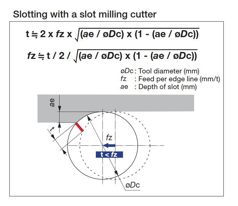
Simple Chip Thickness Calculator
By entering tool diameter DC, radial depth of cut ae, number of teeth z, spindle speed n, and table feed Vf, this tool instantly calculates feed per tooth fz, maximum chip thickness hex, average chip thickness hm, and ae/DC.
ae/DC = ae / DC
hex = 2 × fz × √{(ae/DC) × (1 – ae/DC)}
hm = fz × 2 × (ae/DC) / φ
* Approximate formulas for peripheral milling where ae < DC. For full slotting, set ae = DC, with hex = fz and hm ≒ 2fz/π.
How to Use the Calculator
- Enter your current machining conditions — DC, ae, z, n, and Vf
- If hex is below 0.02 mm, rubbing is a major concern. Consider increasing fz or reducing the number of teeth
- If ae/DC is below 10%, it is often necessary to raise the feed several times higher than the apparent fz to achieve proper cutting
7. Troubleshooting Guide by Symptom
| Symptom | Main Causes | Points to Review |
|---|---|---|
| Chatter | Excessive overhang / sudden engagement / rubbing due to insufficient feed | Shorten overhang, slightly reduce spindle speed, increase fz to make the tool cut, review edge geometry and number of teeth |
| Unstable groove width | Runout / foreign matter during assembly / deflection of thin-walled workpiece | Check spacers and contact surfaces, consider adjustable-width configurations, strengthen workholding |
| Side-wall deflection | Arbor deflection / poor support parallelism / excessive cutting force | Check support parallelism, shorten overhang, review stock removal per pass |
| Edge chipping or premature wear | Chip clogging / impact at entry / uneven load | Improve chip evacuation, reduce feed at entry, reduce runout, review number of teeth |
| Burning or squealing noise | Excessive cutting speed / rubbing due to too low feed / resonance of thin-blade saw | First reduce spindle speed, then adjust to the proper feed. Avoid excessive cutting speeds with thin slitting saws |
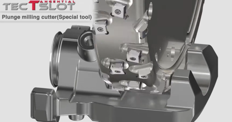
8. Dedicated Slot Mills for Specific Industries ─ The World of Special Form Cutters
Standard catalog items and automatic drawing systems can cover only special shapes that can be expressed parametrically. In actual manufacturing, however, there is a clear demand to finish complex form profiles in a single pass.
This is where fully custom special form cutters come in. Tungaloy has extensive experience in industrial applications such as automotive, construction machinery, energy, and industrial machinery.
POINT
Customization tailored to each industrial application
Automatic drawing systems are designed for speed and standardization. Special form cutters are designed to consolidate complex shapes that standard tools cannot cover into a single tool.
1. Gear Milling Cutters ─ Proven Performance in Construction Machinery, Agricultural Machinery, Industrial Machinery, and Wind Power Gears
- Application: Gear tooth profile machining for gears, spline shafts, serrations, and similar components
- Strength: The tooth profile is built into the cutting edge, enabling tooth-space forming in a single pass. Gear machining can be performed more easily on general-purpose machining centers
- Key appeal: Fully custom design matched to module, number of teeth, pressure angle, and profile shift
2. Cutters for Bracket and Brake Caliper Machining
- Application: Stepped grooves, arc grooves, and complex profile machining of automotive brake calipers, suspension brackets, and chassis components
- Strength: Optimized tooth arrangement design that suppresses chatter in low-rigidity workpieces
- Key appeal: Specification design that balances tool life and dimensional stability in mass-production lines
3. Cutters for Screw Rotor Machining
- Application: Roughing to semi-finishing of male and female rotor grooves for screw compressors, screw pumps, and vacuum pumps
- Strength: Complex screw profiles are form-machined with a dedicated cutting-edge profile
- Key appeal: Fully customized design close to one-of-a-kind tooling for each rotor diameter, lead, and tooth profile. Also supports long tooth heights and complex curves
Extensive Adoption Records Built Across Various Industries
Tungaloy’s special form cutters have been used for many years in mass-production sites across key industries such as automotive, construction machinery, agricultural machinery, industrial machinery, and energy. Through applications including gears, brackets and calipers, and screw rotors, Tungaloy has accumulated design know-how and an extensive application library that address the machining requirements of each industry.
Conclusion
Shapes that cannot be fully expressed by automatic drawing systems are exactly where special form cutters shine
Because Tungaloy has built a proven track record across many industries, it can design cutters optimized for each machining challenge.
Summary ─ Bringing Out the Value of Slot Mills
Slot mills are not “tools only for cut-off and grooving.” They demonstrate their true value in modern machining challenges such as deep grooves, side-wall accuracy, interference avoidance, and side-approach machining on 5-axis machines.
However, because slot mills tend to operate with small ae/DC due to their tool characteristics, understanding chip thickness is the starting point for setting cutting conditions.
- Slot mills are strong in grooving, side-wall machining, cut-off, and interference avoidance
- In grooving, they are often among the most productive options
- Overhang, assembly, and runout determine the finished result
- More teeth are not always better. Check gullet capacity and chip evacuation
- Do not immediately assume that “the tool cannot cut”; first suspect that “the feed rate is too low”
- When ae/DC is small, always check chip thickness
- For shapes that cannot be covered by standard tools or automatic drawing systems, special form cutters can enable process consolidation
Slot mill selection can be considered step by step according to the difficulty of the machining challenge: “standard series / exchangeable-head tools → special tools created through automatic drawing → fully custom special form cutters.” After understanding the basics, consider the option layer that best matches the difficulty of your own machining application.