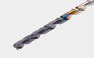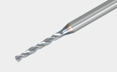
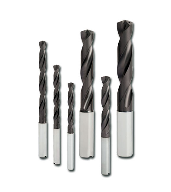
性能稳定的涂层整体硬质合金钻头
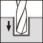
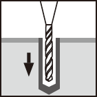
钻头几何形状和合金成分的理想组合,在各种钻孔加工中性能出色
应用 & 特点
应用
DSW 特点
1. 高耐磨性的新型涂层材质
• 新的涂层硬质合金材质具有高通用性。是用于各种材料加工获得长而稳定刀具寿命的完美材质。
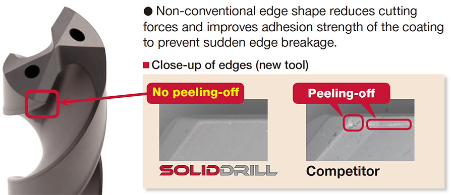
2. 创新的刃口实现可靠的钻孔加工
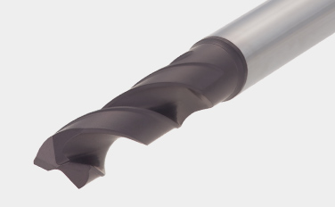
• 非传统的刃口形状减少了切削力并且提高了涂层粘着强度,防止突发的刃口断裂。
3. 全球标准柄类型- DIN6535-Form HA 标准
• 仅有6种柄部直径尺寸可选-ø6, ø8, ø10, ø12, ø14, ø16 mm。这样降低了所需筒夹的种类。

DSM 特点
1. 各种尺寸和 L/D
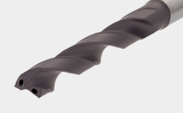
• 允许深孔钻孔深度达5到15倍钻头直径。
• 从ø0.1 到 ø3.0mm直径范围内以0.01mm递增均为标准品。柄部直径均统一为ø3 mm。
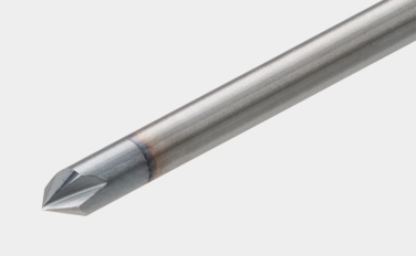
2. 引导孔加工用中心钻
• DSM-CP140 型,拥有140°钻尖角,可以有效防止刃口崩刃。
• DSM-CP90 型,拥有 90°钻尖角,可以用于孔口倒角。
钻体 & 材质
钻体
主要材质
实际案例
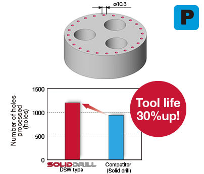
案例 #1
通用工程
| 零件: | 机床零件 |
| 材料: | C55 (ISO) |
| 钻体: | DSW103-040-12DE3 |
| 孔直径: | øDc = 10.3 (mm) |
| 材质: | AH725 |
| 加工条件: | Vc = 50 (m/min) f = 0.3 (mm/rev) H = 24 (mm) 冷却方式: 冷却液(外冷) 机床: 卧式加工中心 |
标准加工条件
DSW-DE (External supply)
| ISO | Workpiece material | Brinell hardness (HB) |
Cutting speedVc (m/min) | Feed: f (mm/rev) | ||||
|---|---|---|---|---|---|---|---|---|
| ø3 – ø6 | ø6 – ø10 | ø10 – ø16 | ø3 – ø6 | ø6 – ø10 | ø10 – ø12 | |||
 |
Low carbon steels (C < 0.3) SS400, SM490, S25C, etc. C15E4, E275A, E355D, etc. |
– 180 | 40 – 100 | 60 – 120 | 60 – 130 | 0.15 – 0.3 | 0.15 – 0.35 | 0.2 – 0.5 |
| Carbon steels (C > 0.3) S45C, S55C, , etc. C45, C55, etc. |
180 – 300 | 40 – 90 | 50 – 120 | 60 – 130 | 0.15 – 0.3 | 0.15 – 0.35 | 0.2 – 0.4 | |
| High alloy steels SCM440, etc. 42CrMo4, etc. |
250 – 350 | 40 – 80 | 50 – 100 | 50 – 100 | 0.1 – 0.2 | 0.15 – 0.3 | 0.15 – 0.35 | |
 |
Stainless steels SUS304, etc. X5CrNi18-9, etc. |
– 200 | 20 – 40 | 30 – 50 | 30 – 60 | 0.05 – 0.2 | 0.1 – 0.25 | 0.1 – 0.3 |
 |
Grey cast irons FC300, etc. 250, etc. |
– 200 | 40 – 90 | 50 – 95 | 50 – 100 | 0.15 – 0.3 | 0.2 – 0.4 | 0.2 – 0.5 |
| Ductile cast irons FCD450, etc. 450-10S, etc. |
– 300 | 30 – 80 | 40 – 90 | 45 – 90 | 0.1 – 0.3 | 0.2 – 0.4 | 0.2 – 0.4 | |
 |
Aluminium alloys ADC12, etc. AlSi11Cu3, etc. |
– | 40 – 90 | 50 – 100 | 50 – 100 | 0.15 – 0.3 | 0.2 – 0.4 | 0.2 – 0.5 |
 |
Titanium alloys Ti-6Al-4V, etc. |
– | 20 – 40 | 20 – 40 | 20 – 40 | 0.1 – 0.2 | 0.15 – 0.25 | 0.15 – 0.4 |
| Heat-resistant alloys, Inconel Inconel 718, etc. |
250 – | 10 – 30 | 10 – 30 | 10 – 30 | 0.03 – 0.07 | 0.05 – 0.1 | 0.07 – 0.12 | |
 |
High hardened steels SKD11, etc. X153CrMoV12, etc. |
– 40HRC | 20 – 40 | 20 – 40 | 20 – 40 | 0.05 – 0.15 | 0.05 – 0.15 | 0.05 – 0.2 |
- The cutting parameters shown in the table are merely a starting guideline for general machining. Values should be varied depending on the power or rigidity of the machine to be used. Optimum conditions should be selected depending on the actual chip control or damage on edges.
- When using the smaller diameter tools in each range, set the feed “f” to the lower recommended values.
- The coolant supply is critical for the provision of stable machining conditions and enhanced tool life. A large coolant volume should be supplied, especially when drilling di! cult-to-cut materials.
- When drilling stainless steel with low machinability such as austenitic stainless steel with a depth deeper than L/D = 3, a pecking cycle or internal coolant supply is recommended.
DSW-DI (Internal supply)
| ISO | Workpiece material | Brinell hardness (HB) |
Cutting speedVc (m/min) | Feed: f (mm/rev) | ||||
|---|---|---|---|---|---|---|---|---|
| ø3 – ø6 | ø6 – ø10 | ø10 – ø16 | ø3 – ø6 | ø6 – ø10 | ø10 – ø12 | |||
 |
Low carbon steels (C < 0.3) SS400, SM490, S25C, etc. C15E4, E275A, E355D, etc. |
– 180 | 70 – 140 | 80 – 160 | 90 – 190 | 0.15 – 0.3 | 0.15 – 0.35 | 0.2 – 0.5 |
| Carbon steels (C > 0.3) S45C, S55C, , etc. C45, C55, etc. |
180 – 300 | 50 – 130 | 70 – 160 | 80 – 170 | 0.15 – 0.3 | 0.15 – 0.35 | 0.2 – 0.4 | |
| High alloy steels SCM440, etc. 42CrMo4, etc. |
250 – 350 | 40 – 100 | 60 – 140 | 60 – 160 | 0.1 – 0.2 | 0.15 – 0.3 | 0.15 – 0.35 | |
 |
Stainless steels SUS304, etc. X5CrNi18-9, etc. |
– 200 | 25 – 75 | 50 – 100 | 50 – 120 | 0.05 – 0.2 | 0.1 – 0.25 | 0.1 – 0.3 |
 |
Grey cast irons FC300, etc. 250, etc. |
– 200 | 80 – 140 | 100 – 160 | 100 – 180 | 0.15 – 0.3 | 0.2 – 0.4 | 0.2 – 0.45 |
| Ductile cast irons FCD450, etc. 450-10S, etc. |
– 300 | 70 – 140 | 80 – 150 | 80 – 170 | 0.1 – 0.3 | 0.2 – 0.4 | 0.2 – 0.45 | |
 |
Aluminium alloys ADC12, etc. AlSi11Cu3, etc. |
– | 60 – 200 | 60 – 200 | 60 – 200 | 0.15 – 0.3 | 0.2 – 0.4 | 0.2 – 0.5 |
 |
Titanium alloys Ti-6Al-4V, etc. |
– | 20 – 60 | 30 – 80 | 30 – 80 | 0.1 – 0.2 | 0.1 – 0.25 | 0.15 – 0.4 |
| Heat-resistant alloys, Inconel Inconel 718, etc. |
250 – | 10 – 30 | 10 – 40 | 10 – 40 | 0.03 – 0.07 | 0.05 – 0.1 | 0.07 – 0.15 | |
 |
High hardened steels SKD11, etc. X153CrMoV12, etc. |
– 40HRC | 20 – 50 | 30 – 60 | 30 – 60 | 0.05 – 0.15 | 0.05 – 0.15 | 0.05 – 0.2 |
- The cutting parameters shown in the table are merely a starting guideline for general machining. Values should be varied depending on the power or rigidity of the machine to be used. Optimum conditions should be selected depending on the actual chip control or damage on edges.
- When using the smaller diameter tools in each range, set the feed “f” to the lower recommended values.
- Oil holes that become blocked may cause drill breakages. A fi lter to prevent the circulation of chips must be used on the coolant supply system.
DSW-CI (16xD, 20xD)
| ISO | Workpiece material | Cutting speed Vc (m/min) |
Feed: f (mm/rev) | ||
|---|---|---|---|---|---|
| Tool diameter: DC (mm) | |||||
| ø3 – ø5 | ø5.1 – ø8 | ø8.1 – ø10 | |||
 |
Low carbon steels (C < 0.3) SS400, SM490, S25C, etc. C15E4, E275A, E355D, etc. |
70 – 90 | 0.1 – 0.18 | 0.1 – 0.2 | 0.1 – 0.25 |
| High carbon steels (C > 0.3) S45C, S55C, etc. C45, C55, etc. |
70 – 90 | 0.1 – 0.18 | 0.1 – 0.2 | 0.1 – 0.25 | |
| Low alloy steels SCM415, etc. 18CrMo4, etc. |
70 – 90 | 0.1 – 0.18 | 0.1 – 0.2 | 0.1 – 0.25 | |
| Alloy steels SCM440, SCr420, etc. 42CrMo4, 20Cr4, etc. |
75 – 85 | 0.08 – 0.14 | 0.08 – 0.18 | 0.12 – 0.2 | |
 |
Stainless steels SUS304, SUS316, etc. X5CrNi18-9, X5CrNiMo17-12-2, etc. |
55 – 65 | 0.04 – 0.12 | 0.08 – 0.16 | 0.1 – 0.18 |
 |
Grey cast irons FC250, etc. GG25, etc. |
80 – 100 | 0.14 – 0.24 | 0.16 – 0.26 | 0.18 – 0.3 |
| Ductile cast irons FCD700, etc. GGG70, etc. |
80 – 100 | 0.14 – 0.24 | 0.16 – 0.26 | 0.18 – 0.3 | |
 |
Titanium alloys Ti-6Al-4V, etc. |
35 – 45 | 0.06 – 0.12 | 0.08 – 0.16 | 0.1 – 0.18 |
| Nickel-based alloys | 30 – 40 | 0.06 – 0.12 | 0.08 – 0.16 | 0.1 – 0.18 | |
DSW-CI (30xD)
| ISO | Workpiece material | Cutting speed Vc (m/min) |
Feed: f (mm/rev) | ||
|---|---|---|---|---|---|
| Tool diameter: DC (mm) | |||||
| ø3 – ø5 | ø5.1 – ø8 | ø8.1 – ø10 | |||
 |
Low carbon steels (C < 0.3) SS400, SM490, S25C, etc. C15E4, E275A, E355D, etc. |
70 – 90 | 0.08 – 0.11 | 0.12 – 0.17 | 0.1 – 0.22 |
| High carbon steels (C > 0.3) S45C, S55C, etc. C45, C55, etc. |
70 – 90 | 0.08 – 0.11 | 0.12 – 0.17 | 0.1 – 0.22 | |
| Low alloy steels SCM415, etc. 18CrMo4, etc. |
70 – 90 | 0.08 – 0.11 | 0.12 – 0.17 | 0.1 – 0.22 | |
| Alloy steels SCM440, SCr420, etc. 42CrMo4, 20Cr4, etc. |
75 – 85 | 0.06 – 0.09 | 0.08 – 0.14 | 0.1 – 0.18 | |
 |
Stainless steels SUS304, SUS316, etc. X5CrNi18-9, X5CrNiMo17-12-2, etc. |
55 – 65 | 0.04 – 0.1 | 0.08 – 0.14 | 0.1 – 0.16 |
 |
Grey cast irons FC250, etc. GG25, etc. |
80 – 100 | 0.14 – 0.22 | 0.16 – 0.26 | 0.18 – 0.25 |
| Ductile cast irons FCD700, etc. GGG70, etc. |
80 – 100 | 0.14 – 0.22 | 0.16 – 0.24 | 0.18 – 0.25 | |
 |
Titanium alloys Ti-6Al-4V, etc. |
35 – 45 | 0.06 – 0.1 | 0.08 – 0.12 | 0.1 – 0.13 |
| Nickel-based alloys | 30 – 40 | 0.06 – 0.1 | 0.08 – 0.12 | 0.08 – 0.13 | |
DSM
| ISO | Workpiece material | Hardness | Cutting speedVc (m/min) | Feed: f (mm/rev) | ||||||
|---|---|---|---|---|---|---|---|---|---|---|
| ø0.1 – ø0.3 | ø0.31 – ø0.5 | ø0.51 – ø3 | ø0.1 – ø0.3 | ø0.31 – ø0.5 | ø0.51 – ø1 | ø1.01 – ø2 | ø2.01 – ø3 | |||
 |
Carbon steels, Alloy steels |
– 300HB | 5 – 20 | 15 – 30 | 25 – 60 | 0.001 – 0.004 | 0.002 – 0.01 | 0.005 – 0.05 | 0.03 – 0.09 | 0.05 – 0.1 |
 |
Stainless steels | – 200HB | 2 – 12 | 6 – 18 | 10 – 20 | 0.0005 – 0.004 | 0.002 – 0.008 | 0.005 – 0.03 | 0.01 – 0.04 | 0.02 – 0.05 |
 |
Grey cast irons | 150 – 250HB | 5 – 15 | 10 – 25 | 20 – 50 | 0.0005 – 0.004 | 0.002 – 0.012 | 0.005 – 0.03 | 0.01 – 0.06 | 0.03 – 0.12 |
| Ductile cast irons | 150 – 250HB | 5 – 15 | 10 – 25 | 20 – 50 | 0.001 – 0.003 | 0.002 – 0.01 | 0.005 – 0.02 | 0.01 – 0.05 | 0.03 – 0.1 | |
 |
Aluminium alloys | – | 10 – 20 | 10 – 30 | 20 – 50 | 0.001 – 0.01 | 0.005 – 0.03 | 0.01 – 0.05 | 0.04 – 0.15 | 0.06 – 0.2 |
| Copper / Brass | – | 10 – 20 | 10 – 30 | 20 – 50 | 0.001 – 0.01 | 0.005 – 0.03 | 0.01 – 0.05 | 0.04 – 0.15 | 0.06 – 0.2 | |
 |
Heat-resistant alloys | – 40HRC | 2 – 6 | 5 – 10 | 8 – 20 | 0.0005 – 0.003 | 0.002 – 0.004 | 0.002 – 0.004 | 0.002 – 0.004 | ※ |
 |
High hardened steels | – 50HRC | 4 – 8 | 6 – 10 | 6 – 16 | 0.0005 – 0.002 | 0.001 – 0.005 | 0.005 – 0.02 | 0.01 – 0.03 | 0.02 – 0.06 |
※ Not recommended
- When the drilling depth is deeper than L/D = 5, use drill pecking every 10 to 50% of the drill diameter.
- The above cutting conditions are applied to when a water soluble cutting fluid is used. For drilling a hole smaller than ø0. 3 mm, use of a starting drill is recommended.
- When setting the drill, the drill runout should be within 0.002 mm on the taper. (Especially for the drill diameter smaller than ø0.5 mm)
DSM-CP
| ISO | Workpiece material | Hardness | Cutting speedVc (m/min) | Feed: f (mm/rev) | |
|---|---|---|---|---|---|
| DSM-CP90 | DSM-CP140 | ||||
 |
Carbon, Mild and Alloy steels | – 300HB | 30 – 80 | 0.01 – 0.06 | 0.03 – 0.08 |
 |
Stainless steels | – 200HB | 15 – 40 | 0.01 – 0.03 | 0.02 – 0.06 |
 |
Grey and ductile cast irons | 150 – 250HB | 30 – 80 | 0.02 – 0.06 | 0.05 – 0.1 |
 |
Aluminium alloys | – | 60 – 120 | 0.02 – 0.1 | 0.05 – 0.15 |
 |
High hardened steels | – 45HRC | 10 – 40 | ※ | 0.01 – 0.05 |
※ Not recommended
- Use DSM-CP140 for drilling hard materials and stainless steel that have work-hardening characteristic.
- The above cutting conditions are designed when using water-soluble cutting fluid, in which case, set the cutting speed to the lower side of the range.
关于该产品的更多信息,请访问我们的线上e-catalog或者下载产品样本:

