

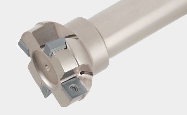
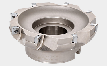
Die beste Lösung für das Fräsen von Stahl und Gusseisen
Eine exakte Simulationsanalyse sorgt für einen leichten Fräser mit geringem Schnittwiderstand und hoher Stabilität

Anwendungen & Eigenschaften
Anwendungen


Eigenschaften
1. Wendeschneidplatten der Sorte CBN für die Hochgeschwindigkeitsbearbeitung von Gusseisen
Sorte mit hohem CBN-Gehalt, bestehend aus extrem dichten mittleren CBN-Körnern

Wendeschneidplatten & Sorten
Wendeschneidplatten
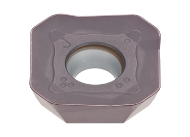
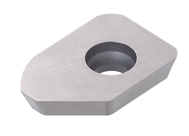
F2-SWGW
- Maximale Schnitttiefe: 0.5 mm
WSGW
- Wiper-Kante
SW*T1304
- Maximale Schnitttiefe: 10 mm
Sorten
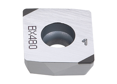
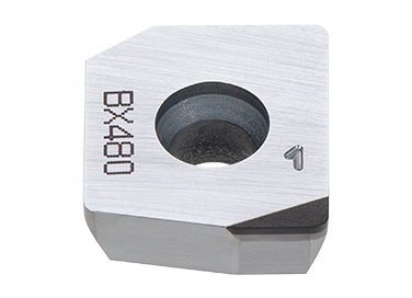
BX480
![]()
- Das härteste CBN
- Ideal für eisenhaltiges Sintermetall
- Geeignet für Hochgeschwindigkeits-Planfräsen von Gusseisen
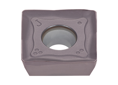
AH130
![]()
- Hohe Ausbruchs- und Bruchsicherheit
- Entwickelt für die Bearbeitung von austenitischem rostfreiem Stahl unter allgemeinen Schnittbedingungen
AH3135
![]()
- Hohe Bruchsicherheit
- Geeignet für die Bearbeitung von Stahl und rostfreiem Stahl unter allgemeinen Schnittbedingungen
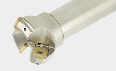
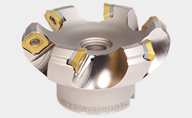
Fräs-Körper
Praxis-Beispiele
Beispiel 1
| Werkstück: | Zylinderblock |
| Material: | FC250 / 250 |
| Fräser: | TPW13R125M38.1-08 (DCX = 125 mm, CICT = 8) |
| Wendeschneidplatte: | 2-SWGW130508PDLSR x6, WSGW130508PDLSR x2 |
| Sorte: | BX480 |
| Schnittbedingungen: | Vc = 800 (m/min) fz = 0.11 (mm/Z) Vf = 1,760 (mm/min) ap = 0.2 (mm) ae = ~ 80 (mm) Anwendung: Planfräsen Kühlmittel: Trocken Maschine: Horizontal M/C, KM100 |

Beispiel 2
| Werkstück: | Zylinderblock |
| Material: | FC250 / 250 |
| Fräser: | TPW13 Fräser (maßgeschneidert, DCX = 250 mm, CICT = 12) |
| Wendeschneidplatte: | 2-SWGW130508PDLSR x10, WSGW130508PDLSR x2 |
| Sorte: | BX480 |
| Schnittbedingungen: | Vc = 1,178 ~ 1,257 (m/min) fz = 0.05 ~ 0.11 (mm/Z) Vf = 900 ~ 1,980 (mm/min) ap = 0.2 (mm) ae = ~ 200 (mm) Anwendung: Planfräsen Kühlmittel: Trocken Maschine: Horizontal M/C, KM100 |

Beispiel 3
| Werkstück: | Hydraulischer Teil |
| Material: | Chrom-Molybdän-Stahl (SCM415) |
| Fräser: | TPW13R080M25.4-04 (ø80, z=4) |
| Wendeschneidplatte: | SWMT1304PDPR-MS |
| Sorte: | AH140 |
| Bedingungen: | Vc = 120 (m/min) fz = 0.18 (mm/Z) Vf = 350 (mm/min) ap = 1.2 (mm) ae = ~ 50 (mm) Anwendung: Planfräsen Kühlmittel: Trocken Maschine: – |

Standard-Schnittbedingungen
TAW13, EAW13
| ISO | Workpiece materials |
Hardness | Priority | Grade | Cutting speed Vc(m/min) |
Roughing (Depth of cut ≥ 1.0 mm) | |||||
|---|---|---|---|---|---|---|---|---|---|---|---|
| Feed per tooth:fz (mm/t) | |||||||||||
| MJ | ML | HJ | MS | Flat top | AJ | ||||||
 |
Mild steel Low carbon steel |
< 180 HB | First choice | AH3225 (AH3135) |
100 – 270 | 0.05 – 0.3 | 0.05 – 0.25 | 0.2 – 0.6 | – | 0.05 – 0.3 | – |
| < 180 HB | Wear resistance | T3225 | 150 – 300 | 0.05 – 0.3 | – | 0.2 – 0.6 | – | 0.05 – 0.3 | – | ||
| < 180 HB | Surface quality | NS740 | 100 – 300 | 0.05 – 0.23 | – | – | – | 0.05 – 0.23 | – | ||
| Carbon steel Alloy steel |
< 300 HB | First choice | AH3225 (AH3135) |
100 – 230 | 0.05 – 0.25 | 0.05 – 0.2 | 0.2 – 0.5 | – | 0.05 – 0.25 | – | |
| < 300 HB | Wear resistance | T3225 | 150 – 280 | 0.05 – 0.25 | – | 0.2 – 0.5 | – | 0.05 – 0.25 | – | ||
| < 300 HB | Surface quality | NS740 | 100 – 230 | 0.05 – 0.2 | – | – | – | 0.05 – 0.2 | – | ||
| Die steel | < 30 HRC | First choice | AH3225 (AH3135) |
100 – 180 | 0.05 – 0.2 | 0.05 – 0.2 | 0.2 – 0.4 | – | 0.05 – 0.2 | – | |
| < 30 HRC | Wear resistance | T3225 | 100 – 180 | 0.05 – 0.2 | – | 0.2 – 0.4 | – | 0.05 – 0.2 | – | ||
 |
Stainless steel | < 250 HB | First choice | AH3135 | 80 – 200 | 0.1 – 0.25 | 0.1 – 0.2 | 0.2 – 0.5 | 0.1 – 0.2 | – | – |
| < 250 HB | Wear resistance | T3225 | 150 – 250 | 0.1 – 0.25 | 0.1 – 0.2 | 0.2 – 0.5 | – | 0.1 – 0.25 | – | ||
 |
Grey cast iron | 150 – 250 HB | First choice | AH8015 (AH120) |
150 – 250 | 0.05 – 0.25 | 0.05 – 0.2 | 0.2 – 0.6 | – | 0.05 – 0.25 | – |
| 150 – 250 HB | Wear resistance | T1215 | 180 – 300 | 0.05 – 0.25 | – | 0.2 – 0.6 | – | 0.05 – 0.25 | – | ||
| Ductile cast iron | 150 – 250 HB | First choice | AH8015 (AH120) |
100 – 180 | 0.05 – 0.25 | 0.05 – 0.2 | 0.2 – 0.6 | – | 0.05 – 0.25 | – | |
| 150 – 250 HB | Wear resistance | T1215 | 120 – 200 | 0.05 – 0.25 | – | 0.2 – 0.6 | – | 0.05 – 0.25 | – | ||
 |
Aluminium alloys Si < 13% |
– | First choice | DS2005 KS05F |
300 – 1000 | – | – | – | – | – | 0.05 – 0.2 |
| – | Wear resistance | DX140 | 200 – 800 | – | – | – | – | – | 0.05 – 0.2 | ||
| Aluminium alloys Si ≥ 13% |
– | First choice | DS2005 KS05F |
80 – 300 | – | – | – | – | – | 0.05 – 0.2 | |
| – | Wear resistance | DX140 | 200 – 800 | – | – | – | – | – | 0.05 – 0.2 | ||
| Copper alloys | – | First choice | DS2005 KS05F |
200 – 500 | – | – | – | – | – | 0.05 – 0.2 | |
| – | Wear resistance | DX140 | 200 – 800 | – | – | – | – | – | 0.05 – 0.2 | ||
 |
Titanium alloys Ti-6Al-4V, etc. |
– 40 HRC | First choice | AH130 | 30 – 60 | 0.1 – 0.25 | – | 0.2 – 0.5 | 0.1 – 0.2 | – | – |
| Heat-resistance alloys Inconel 718, etc. |
– 40 HRC | First choice | AH8015 (AH120) |
20 – 50 | 0.05 – 0.15 | – | 0.1 – 0.3 | – | – | – | |
 |
Hardened steel SKD61, etc. X40CrMoV5-1, etc. |
40 – 50HRC | First choice | AH8015 (AH120) |
45 – 70 | 0.08 – 0.15 | – | 0.1 – 0.3 | – | – | – |
– When using an aggressive depth of cut (for AP or AE), set the Vc and/or fz to the lower side of the value shown in the table.
– Dry cutting (or compressed air) is generally recommended. When excessive chip welding occurs on the cutting edge such as during stainless steel machining, use a water soluble cutting fluid and reduce Vc.
– When wet machining mild steel, carbon steel, or alloy steel, reduce the Vc and/or fz.
– Do not use TAW13 cutters for ramping, plunging, or drilling application as they are not designed for feeding in the Z axis direction.
| ISO | Workpiece materials |
Hardness | Priority | Grade | Cutting speed Vc (m/min) |
Light cutting to finishing (Depth of cut < 1.0 mm) | ||||||
|---|---|---|---|---|---|---|---|---|---|---|---|---|
| Feed per tooth:fz (mm/t) | ||||||||||||
| MJ | ML | HJ | MS | Flat top | AJ | |||||||
|
Mild steel Low carbon steel |
< 180 HB | First choice | AH3225 (AH3135) |
100 – 270 | 0.05 – 0.25 | 0.05 – 0.2 | 0.2 – 0.6 | – | 0.05 – 0.25 | – | |
| < 180 HB | Wear resistance | T3225 | 150 – 300 | 0.05 – 0.25 | – | 0.2 – 0.6 | – | 0.05 – 0.25 | – | |||
| < 180 HB | Surface quality | NS740 | 100 – 300 | 0.05 – 0.2 | – | – | – | 0.05 – 0.23 | – | |||
| Carbon steel Alloy steel |
< 300 HB | First choice | AH3225 (AH3135) |
100 – 230 | 0.05 – 0.2 | 0.05 – 0.25 | 0.2 – 0.5 | – | 0.05 – 0.2 | – | ||
| < 300 HB | Wear resistance | T3225 | 150 – 280 | 0.05 – 0.2 | – | 0.2 – 0.5 | – | 0.05 – 0.2 | – | |||
| < 300 HB | Surface quality | NS740 | 100 – 230 | 0.05 – 0.18 | – | – | – | 0.05 – 0.18 | – | |||
| Die steel | < 30 HRC | First choice | AH3225 (AH3135) |
100 – 180 | 0.05 – 0.18 | 0.05 – 0.12 | 0.2 – 0.4 | – | 0.05 – 0.18 | – | ||
| < 30 HRC | Wear resistance | T3225 | 100 – 180 | 0.05 – 0.18 | – | 0.2 – 0.4 | – | 0.05 – 0.18 | – | |||
|
Stainless steel | < 250 HB | First choice | AH3135 | 80 – 200 | 0.1 – 0.2 | 0.1 – 0.18 | 0.2 – 0.5 | 0.1 – 0.18 | – | – | |
| < 250 HB | Wear resistance | T3225 | 150 – 250 | 0.1 – 0.2 | 0.1 – 0.18 | 0.2 – 0.5 | – | 0.1 – 0.2 | – | |||
|
Grey cast iron | 150 – 250 HB | First choice | AH8015 (AH120) |
150 – 250 | 0.1 – 0.2 | 0.05 – 0.18 | 0.2 – 0.6 | – | 0.1 – 0.2 | – | |
| 150 – 250 HB | Wear resistance | T1215 | 180 – 300 | 0.1 – 0.2 | – | 0.2 – 0.6 | – | 0.1 – 0.2 | – | |||
| Ductile cast iron | 150 – 250 HB | First choice | AH8015 (AH120) |
100 – 180 | 0.1 – 0.2 | 0.05 – 0.18 | 0.2 – 0.6 | – | 0.1 – 0.2 | – | ||
| 150 – 250 HB | Wear resistance | T1215 | 120 – 200 | 0.1 – 0.2 | – | 0.2 – 0.6 | – | 0.1 – 0.2 | – | |||
|
Aluminium alloys Si < 13% |
– | First choice | DS2005 KS05F |
300 – 1000 | – | – | – | – | – | 0.05 – 0.2 | |
| – | Wear resistance | DX140 | 200 – 800 | – | – | – | – | – | 0.05 – 0.2 | |||
| Aluminium alloys Si ≥ 13% |
– | First choice | DS2005 KS05F |
80 – 300 | – | – | – | – | – | 0.05 – 0.2 | ||
| – | Wear resistance | DX140 | 200 – 800 | – | – | – | – | – | 0.05 – 0.2 | |||
| Copper alloys | – | First choice | DS2005 KS05F |
200 – 500 | – | – | – | – | – | 0.05 – 0.2 | ||
| – | Wear resistance | DX140 | 200 – 800 | – | – | – | – | – | 0.05 – 0.2 | |||
|
Titanium alloys Ti-6Al-4V, etc. |
– 40 HRC | First choice | AH130 | 30 – 60 | 0.1 – 0.21 | – | 0.2 – 0.5 | 0.1 – 0.2 | – | – | |
| Heat-resistance alloys Inconel 718, etc. |
– 40 HRC | First choice | AH8015 (AH120) |
20 – 50 | 0.05 – 0.15 | – | 0.1 – 0.3 | – | – | – | ||
|
Hardened steel |
SKD61, etc. X40CrMoV5-1, etc. |
40 – 50HRC | First choice | AH8015 (AH120) |
45 – 70 | 0.08 – 0.15 | – | 0.1 – 0.3 | – | – | – |
| SKD11, etc. X153CrMoV12, etc. |
50 – 60HRC | First choice | AH8015 (AH120) |
40 – 65 | 0.05 – 0.1 | – | 0.05 – 0.14 | – | – | – | ||
– When using an aggressive depth of cut (for AP or AE), set the Vc and/or fz to the lower side of the value shown in the table.
– Dry cutting (or compressed air) is generally recommended. When excessive chip welding occurs on the cutting edge such as during stainless steel machining, use a water soluble cutting fluid and reduce Vc.
– When wet machining mild steel, carbon steel, or alloy steel, reduce the Vc and/or fz.
– Do not use TAW13 cutters for ramping, plunging, or drilling application as they are not designed for feeding in the Z axis direction.
TPW13, EPW13
| ISO | Workpiece materials |
Hardness | Priority | Grade | Cutting speed Vc (m/min) |
Roughing (Depth of cut ≥ 1.0 mm) | ||||
|---|---|---|---|---|---|---|---|---|---|---|
| Feed per tooth:fz (mm/t) | ||||||||||
| MJ | ML | MS | AJ | |||||||
|
Mild steel Low carbon steel |
< 180 HB | First choice | AH3225 (AH3135) |
100 – 270 | 0.05 – 0.25 | 0.05 – 0.2 | – | – | |
| < 180 HB | Wear resistance | T3225 | 150 – 300 | 0.05 – 0.25 | – | – | – | |||
| < 180 HB | Fracture resistance | AH3135 | 80 – 180 | 0.05 – 0.25 | – | 0.05 – 0.2 | – | |||
| < 180 HB | Surface finish | NS740 | 100 – 300 | 0.05 – 0.15 | – | – | – | |||
| Carbon steel Alloy steel |
< 300 HB | First choice | AH3225 (AH3135) |
100 – 230 | 0.05 – 0.2 | 0.05 – 0.15 | – | – | ||
| < 300 HB | Wear resistance | T3225 | 150 – 280 | 0.05 – 0.2 | – | – | – | |||
| < 300 HB | Fracture resistance | AH3135 | 80 – 150 | 0.05 – 0.2 | – | – | – | |||
| < 300 HB | Surface finish | NS740 | 100 – 230 | 0.05 – 0.15 | – | – | – | |||
| Die steel | < 30 HRC | First choice | AH3225 (AH3135) |
100 – 180 | 0.05 – 0.15 | 0.05 – 0.12 | – | – | ||
| < 30 HRC | Wear resistance | T3225 | 100 – 180 | 0.05 – 0.15 | – | – | – | |||
|
Stainless steel | < 50 HB | First choice | AH3135 | 80 – 200 | 0.05 – 0.2 | – | 0.05 – 0.18 | – | |
| < 50 HB | Wear resistance | T3225 | 150 – 250 | 0.05 – 0.2 | – | – | – | |||
|
Grey cast iron | 150 – 250 HB | First choice | AH8015 (AH120) |
100 – 250 | 0.05 – 0.2 | 0.05 – 0.15 | – | – | |
| 150 – 250 HB | Wear resistance | T1215 | 100 – 250 | 0.05 – 0.2 | – | – | – | |||
| 150 – 250 HB | Use when high efficiency milling is required |
BX480 | 800 – 1500 | 0.05 – 0.3 (F2-SWGW1305) |
– | – | – | |||
| Ductile cast iron | 150 – 250 HB | First choice | AH8015 (AH120) |
100 – 250 | 0.05 – 0.2 | 0.05 – 0.15 | – | – | ||
| 150 – 250 HB | Wear resistance | T1215 | 100 – 250 | 0.05 – 0.2 | – | – | – | |||
|
Aluminium alloys Si < 13% |
– | First choice | DS2005 KS05F |
300 – 1000 | – | – | – | 0.05 – 0.2 | |
| Aluminium alloys Si ≥ 13% |
– | First choice | DS2005 KS05F |
80 – 300 | – | – | – | 0.05 – 0.2 | ||
| Copper alloys | – | First choice | DS2005 KS05F |
200 – 500 | – | – | – | 0.05 – 0.2 | ||
|
Titanium alloys Ti-6Al-4V, etc. |
– 40 HRC | First choice | AH130 | 30 – 60 | 0.1 – 0.25 | – | 0.1 – 0.2 | – | |
| Heat-resistance alloys Inconel 718, etc. |
– 40 HRC | First choice | AH8015 (AH120) |
20 – 50 | 0.05 – 0.15 | 0.05 – 0.1 | – | – | ||
|
Hardened steel |
SKD61, etc. X40CrMoV5-1, etc. |
40 – 50HRC | First choice | AH8015 (AH120) |
45 – 70 | 0.08 – 0.15 | – | – | – |
| SKD11, etc. X153CrMoV12, etc. |
50 – 60HRC | First choice | AH8015 (AH120) |
40 – 65 | 0.06 – 0.1 | – | – | – | ||
– When using an aggressive depth of cut (for AP or AE), set the Vc and/or fz to the lower side of the value shown in the table.
– Dry cutting (or compressed air) is generally recommended. When excessive chip welding occurs on the cutting edge such as during stainless steel machining, use a water soluble cutting fluid and reduce Vc.
– When wet machining mild steel, carbon steel, or alloy steel, reduce the Vc and/or fz.
– Do not use TPW13 cutters for ramping, plunging, or drilling application as they are not designed for feeding in the Z axis direction.
| ISO | Workpiece materials |
Hardness | Priority | Grade | Cutting speed Vc (m/min) |
Light cutting to fi nishing (Depth of cut < 1.0 mm) | |||
|---|---|---|---|---|---|---|---|---|---|
| Feed per tooth:fz (mm/t) | |||||||||
| MJ | ML | MS | AJ | ||||||
|
Mild steel Low carbon steel |
< 180 HB | First choice | AH3225 (AH3135) |
100 – 270 | 0.05 – 0.2 | 0.05 – 0.18 | – | – |
| < 180 HB | Wear resistance | T3225 | 150 – 300 | 0.05 – 0.2 | – | – | – | ||
| < 180 HB | Fracture resistance | AH3135 | 80 – 180 | 0.05 – 0.2 | – | 0.05 – 0.18 | – | ||
| < 180 HB | Surface finish | NS740 | 100 – 300 | 0.05 – 0.12 | – | – | – | ||
| Carbon steel Alloy steel |
< 300 HB | First choice | AH3225 (AH3135) |
100 – 230 | 0.05 – 0.18 | 0.05 – 0.12 | – | – | |
| < 300 HB | Wear resistance | T3225 | 150 – 280 | 0.05 – 0.18 | – | – | – | ||
| < 300 HB | Fracture resistance | AH3135 | 80 – 150 | 0.05 – 0.18 | – | – | – | ||
| < 300 HB | Surface finish | NS740 | 100 – 230 | 0.05 – 0.12 | – | – | – | ||
| Die steel | < 30 HRC | First choice | AH3225 (AH3135) |
100 – 180 | 0.05 – 0.12 | 0.05 – 0.1 | – | – | |
| < 30 HRC | Wear resistance | T3225 | 100 – 180 | 0.05 – 0.12 | – | – | – | ||
|
Stainless steel | < 50 HB | First choice | AH3135 | 80 – 200 | 0.05 – 0.18 | – | 0.05 – 0.15 | – |
| < 50 HB | Wear resistance | T3225 | 150 – 250 | 0.05 – 0.18 | – | – | – | ||
|
Grey cast iron | 150 – 250 HB | First choice | AH8015 (AH120) |
100 – 250 | 0.05 – 0.18 | 0.05 – 0.12 | – | – |
| 150 – 250 HB | Wear resistance | T1215 | 100 – 250 | 0.05 – 0.18 | – | – | – | ||
| Ductile cast iron | 150 – 250 HB | First choice | AH8015 (AH120) |
100 – 250 | 0.05 – 0.18 | 0.05 – 0.12 | – | – | |
| 150 – 250 HB | Wear resistance | T1215 | 100 – 250 | 0.05 – 0.18 | – | – | – | ||
|
Aluminium alloys Si < 13% |
– | First choice | DS2005 KS05F |
300 – 1000 | – | – | – | 0.05 – 0.2 |
| Aluminium alloys Si ≥ 13% |
– | First choice | DS2005 KS05F |
80 – 300 | – | – | – | 0.05 – 0.2 | |
| Copper alloys | – | First choice | DS2005 KS05F |
200 – 500 | – | – | – | 0.05 – 0.2 | |
|
Titanium alloys Ti-6Al-4V, etc. |
– 40 HRC | First choice | AH130 | 30 – 60 | 0.1 – 0.25 | – | 0.1 – 0.25 | – |
| Heat-resistance alloys Inconel 718, etc. |
– 40 HRC | First choice | AH8015 (AH120) |
20 – 50 | 0.05 – 0.15 | 0.05 – 0.1 | – | – | |
|
Hardened SKD61, etc. X40CrMoV5-1, etc. |
40 – 50HRC | First choice | AH8015 (AH120) |
45 – 70 | 0.05 – 0.15 | – | – | – |
– When using an aggressive depth of cut (for AP or AE), set the Vc and/or fz to the lower side of the value shown in the table.
– Dry cutting (or compressed air) is generally recommended. When excessive chip welding occurs on the cutting edge such as during stainless steel machining, use a water soluble cutting fluid and reduce Vc.
– When wet machining mild steel, carbon steel, or alloy steel, reduce the Vc and/or fz.
– Do not use TPW13 cutters for ramping, plunging, or drilling application as they are not designed for feeding in the Z axis direction.
Weitere Informationen zu diesem Produkt finden Sie in unserem Online-Katalog oder im Produktbericht, den Sie herunterladen können:
Metrisch

Industrie Lösungen |
|
Industrie Lösungen Weiter lesen |

e-Catalog |
|
e-Catalog Weiter lesen |
Ressourcen
 Tungaloy APP
 TUNG NaviWerkzeugempfehlungen für Ihren spezifischen Bedarf
 Machine Power Calculator
 Turning Insert Selection Guide
 Tungaloy ErfolgsberichtEntdecken Sie Tungaloys TSR für Einblicke in die individuelle Bearbeitung mit einfacher Suche
 Technische AnleitungenTungaloys technische Anleitungen bieten wertvolle Einblicke, Referenzen und Ressourcen.
 MatrixWerkzeug-Management-System
 Special tool drawing generatorQuickly generate simple drawings for special products.