

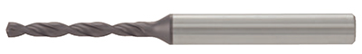
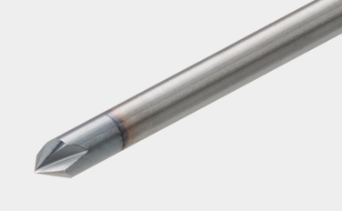
Beschichteter Vollhartmetallbohrer für hervorragende Stabilität
Ideale Kombination von Bohrergeometrie und Hartmetallzusammensetzung für außergewöhnliche Leistung bei einer Vielzahl von Bohranwendungen

Anwendungen & Eigenschaften
Anwendungen

Eigenschaften für DSW
1. Neue beschichtete Sorte mit stark verbesserter Verschleißfestigkeit
- Neue beschichtete Hartmetallsorte mit einem hohen Maß an Vielseitigkeit. Perfekte Sorte für stabile und lange Standzeiten bei einer Vielzahl von Werkstoffen.
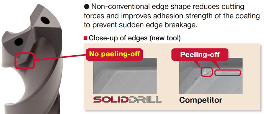
2. Innovative Schneidkante bietet zuverlässiges Bohren
• Die unkonventionelle Kantenform reduziert die Schnittkräfte und verbessert die Haftfestigkeit der Beschichtung, um einen plötzlichen Kantenbruch zu verhindern.
3. Weltweite Standard-Schaftform – Genormt nach DIN6535-Form HA
• Nur 6 Schaftdurchmesser verfügbar – ø6, ø8, ø10, ø12, ø14, ø16 mm. Dadurch wird die Anzahl der benötigten Spannzangen reduziert.
Eigenschaften für DSM
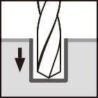
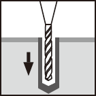
1. Unterschiedliche Abmessungen und L/D
• Ermöglicht Tieflochbohrungen bis zum 5- bis 15-fachen des Bohrdurchmessers.
• Erhältlich als Standardartikel von ø0,1 bis ø3,0 mm in 0,01-mm-Schritten. Die Schaftdurchmesser sind alle auf ø3 mm vereinheitlicht.
2. Zentrierbohrer für die Bearbeitung von Führungslöchern
• Der Typ DSM-CP140 hat einen Spitzenwinkel von 140°, der ein Abplatzen der Schneide wirksam verhindern kann.
• Der Typ DSM-CP90, der einen Spitzenwinkel von 90° hat, kann auch zum Anfasen des Lochrandes verwendet werden.
Bohrkörper & Sorten
Bohrkörper
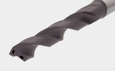
DSW-DI (ø3 – ø12 mm)
- Typ mit Kühlmittelbohrung
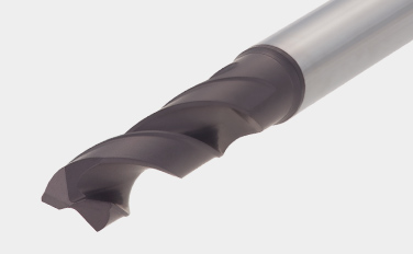
DSW-DE (ø3 – ø12 mm)
- Ohne Kühlmittelbohrung. Wirtschaftlicher Typ.
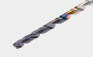
DSW-CI (ø3 – ø10 mm)
- Cylindrical shank, with coolant holes
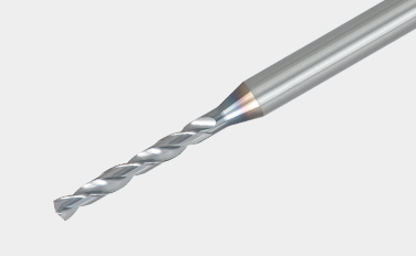
DSM (ø0.1 – ø3 mm)
- Vollhartmetallbohrer mit kleinem Durchmesser, L/D (ULDR) = 5 – 15
DSM-CP (ø3 mm)
- Bohrer für Zentrierloch
Haupt-Sorten
AH725
![]()
![]()
![]()
![]()
- P15 – P30 / M15 – M30 / K25 – K30 / S15 – S25
- Gutes Gleichgewicht zwischen Verschleiß- und Zerspanungsfestigkeit
- Geeignet für die Bearbeitung von Stahl und rostfreiem Stahl unter allgemeinen Zerspanungsbedingungen
YH170
![]()
![]()
- P20 – P35 / M20 – M35
- Hohe Verschleiß- und Bruchsicherheit
- Entwickelt für das Bohren von Kohlenstoffstahl und rostfreiem Stahl
YH180
![]()
![]()
- Hohe Verschleißfestigkeit
- Entwickelt für das Bohren von Kohlenstoffstahl und rostfreiem Stahl
Praxis-Beispiele
Beispiel 1
Allgemeiner Maschinenbau
| Werkstück: | Maschinenteile |
| Material: | C55 (ISO) |
| Bohrkörper: | DSW103-040-12DE3 |
| Durchmesser der Bohrung: | øDc = 10.3 (mm) |
| Sorte: | AH725 |
| Schnittbedingungen: | Vc = 50 (m/min) f = 0.3 (mm/U) H = 24 (mm) Kühlmittel: Nass (extern) Maschine: Horizontal MC |

Standard-Schnittbedingungen
DSW-DE (Externe Kühlmittelzufuhr)
| ISO | Material des Werkstücks | Brinell-Härte (HB) |
Schnittgeschw. Vc (m/min) | Vorschub: f (mm/U) | ||||
|---|---|---|---|---|---|---|---|---|
| ø3 – ø6 | ø6 – ø10 | ø10 – ø16 | ø3 – ø6 | ø6 – ø10 | ø10 – ø12 | |||
 |
Stähle mit niedrigem Kohlenstoffgehalt (C < 0.3) SS400, SM490, S25C, etc. C15E4, E275A, E355D, etc. |
– 180 | 40 – 100 | 60 – 120 | 60 – 130 | 0.15 – 0.3 | 0.15 – 0.35 | 0.2 – 0.5 |
| Kohlenstoffstähle (C > 0.3) S45C, S55C, , etc. C45, C55, etc. |
180 – 300 | 40 – 90 | 50 – 120 | 60 – 130 | 0.15 – 0.3 | 0.15 – 0.35 | 0.2 – 0.4 | |
| Hochlegierte Stähle SCM440, etc. 42CrMo4, etc. |
250 – 350 | 40 – 80 | 50 – 100 | 50 – 100 | 0.1 – 0.2 | 0.15 – 0.3 | 0.15 – 0.35 | |
 |
Rostfreie Stähle SUS304, etc. X5CrNi18-9, etc. |
– 200 | 20 – 40 | 30 – 50 | 30 – 60 | 0.05 – 0.2 | 0.1 – 0.25 | 0.1 – 0.3 |
 |
Grauguss FC300, etc. 250, etc. |
– 200 | 40 – 90 | 50 – 95 | 50 – 100 | 0.15 – 0.3 | 0.2 – 0.4 | 0.2 – 0.5 |
| Kugelgraphitguss FCD450, etc. 450-10S, etc. |
– 300 | 30 – 80 | 40 – 90 | 45 – 90 | 0.1 – 0.3 | 0.2 – 0.4 | 0.2 – 0.4 | |
 |
Aluminium-Legierungen ADC12, etc. AlSi11Cu3, etc. |
– | 40 – 90 | 50 – 100 | 50 – 100 | 0.15 – 0.3 | 0.2 – 0.4 | 0.2 – 0.5 |
 |
Titan-Legierungen Ti-6Al-4V, etc. |
– | 20 – 40 | 20 – 40 | 20 – 40 | 0.1 – 0.2 | 0.15 – 0.25 | 0.15 – 0.4 |
| Hitzebeständige Legierungen Inconel 718, etc. |
250 – | 10 – 30 | 10 – 30 | 10 – 30 | 0.03 – 0.07 | 0.05 – 0.1 | 0.07 – 0.12 | |
 |
Hochgehärtete Stähle SKD11, etc. X153CrMoV12, etc. |
– 40HRC | 20 – 40 | 20 – 40 | 20 – 40 | 0.05 – 0.15 | 0.05 – 0.15 | 0.05 – 0.2 |
- Die in der Tabelle angegebenen Schnittparameter sind lediglich ein Richtwert für die allgemeine Bearbeitung. Die Werte sollten in Abhängigkeit von der Leistung oder Stabilität der zu verwendenden Maschine variiert werden. Die optimalen Bedingungen sollten in Abhängigkeit von der tatsächlichen Spankontrolle oder Beschädigung der Kanten gewählt werden.
- Bei der Verwendung von Werkzeugen mit kleinerem Durchmesser in jedem Bereich ist der Vorschub „f“ auf die niedrigeren empfohlenen Werte einzustellen.
- Die Kühlmittelzufuhr ist von entscheidender Bedeutung für die Gewährleistung stabiler Bearbeitungsbedingungen und einer höheren Werkzeugstandzeit. Insbesondere beim Bohren von schwer zerspanbaren Werkstoffen sollte eine große Kühlmittelmenge zugeführt werden.
- Beim Bohren von rostfreiem Stahl mit geringer Zerspanbarkeit, wie z. B. austenitischem rostfreiem Stahl mit einer Tiefe von mehr als L/D = 3, wird ein Picking-Zyklus oder eine innere Kühlmittelzufuhr empfohlen.
DSW-DI (Interne Kühlmittelzufuhr)
| ISO | Material des Werkstücks | Brinell-Härte (HB) |
Schnittgeschw. Vc (m/min) | Vorschub: f (mm/U) | ||||
|---|---|---|---|---|---|---|---|---|
| ø3 – ø6 | ø6 – ø10 | ø10 – ø16 | ø3 – ø6 | ø6 – ø10 | ø10 – ø12 | |||
|
Stähle mit niedrigem Kohlenstoffgehalt (C < 0.3) SS400, SM490, S25C, etc. C15E4, E275A, E355D, etc. |
– 180 | 70 – 140 | 80 – 160 | 90 – 190 | 0.15 – 0.3 | 0.15 – 0.35 | 0.2 – 0.5 |
| Kohlenstoffstähle (C > 0.3) S45C, S55C, , etc. C45, C55, etc. |
180 – 300 | 50 – 130 | 70 – 160 | 80 – 170 | 0.15 – 0.3 | 0.15 – 0.35 | 0.2 – 0.4 | |
| Hochlegierte Stähle SCM440, etc. 42CrMo4, etc. |
250 – 350 | 40 – 100 | 60 – 140 | 60 – 160 | 0.1 – 0.2 | 0.15 – 0.3 | 0.15 – 0.35 | |
|
Rostfreie Stähle SUS304, etc. X5CrNi18-9, etc. |
– 200 | 25 – 75 | 50 – 100 | 50 – 120 | 0.05 – 0.2 | 0.1 – 0.25 | 0.1 – 0.3 |
|
Grauguss FC300, etc. 250, etc. |
– 200 | 80 – 140 | 100 – 160 | 100 – 180 | 0.15 – 0.3 | 0.2 – 0.4 | 0.2 – 0.45 |
| Kugelgraphitguss FCD450, etc. 450-10S, etc. |
– 300 | 70 – 140 | 80 – 150 | 80 – 170 | 0.1 – 0.3 | 0.2 – 0.4 | 0.2 – 0.45 | |
|
Aluminium-Legierungen ADC12, etc. AlSi11Cu3, etc. |
– | 60 – 200 | 60 – 200 | 60 – 200 | 0.15 – 0.3 | 0.2 – 0.4 | 0.2 – 0.5 |
|
Titan-Legierungen Ti-6Al-4V, etc. |
– | 20 – 60 | 30 – 80 | 30 – 80 | 0.1 – 0.2 | 0.1 – 0.25 | 0.15 – 0.4 |
| Hitzebeständige Legierungen Inconel 718, etc. |
250 – | 10 – 30 | 10 – 40 | 10 – 40 | 0.03 – 0.07 | 0.05 – 0.1 | 0.07 – 0.15 | |
|
Hochgehärtete Stähle SKD11, etc. X153CrMoV12, etc. |
– 40HRC | 20 – 50 | 30 – 60 | 30 – 60 | 0.05 – 0.15 | 0.05 – 0.15 | 0.05 – 0.2 |
- Die in der Tabelle angegebenen Schnittparameter sind lediglich ein Richtwert für die allgemeine Bearbeitung. Die Werte sollten in Abhängigkeit von der Leistung oder Stabilität der zu verwendenden Maschine variiert werden. Die optimalen Bedingungen sollten in Abhängigkeit von der tatsächlichen Spankontrolle oder Beschädigung der Kanten gewählt werden.
- Bei Verwendung von Werkzeugen mit kleinerem Durchmesser in jedem Bereich ist der Vorschub „f“ auf die niedrigeren empfohlenen Werte einzustellen.
- Ölbohrungen können zu Bohrerbrüchen führen. In der Kühlmittelzufuhr muss ein Filter verwendet werden, der die Zirkulation von Spänen verhindert.
DSW-CI (16xD, 20xD)
| ISO | Material des Werkstücks | Schnittgeschw. Vc (m/min) |
Vorschub: f (mm/U) | ||
|---|---|---|---|---|---|
| Werkzeug-Durchmesser: DC (mm) | |||||
| ø3 – ø5 | ø5.1 – ø8 | ø8.1 – ø10 | |||
|
Stähle mit niedrigem Kohlenstoffgehalt (C < 0.3) SS400, SM490, S25C, etc. C15E4, E275A, E355D, etc. |
70 – 90 | 0.1 – 0.18 | 0.1 – 0.2 | 0.1 – 0.25 |
| Stähle mit hohem Kohlenstoffgehalt (C > 0.3) S45C, S55C, etc. C45, C55, etc. |
70 – 90 | 0.1 – 0.18 | 0.1 – 0.2 | 0.1 – 0.25 | |
| Stähle mit niedrigem Legierungsgehalt SCM415, etc. 18CrMo4, etc. |
70 – 90 | 0.1 – 0.18 | 0.1 – 0.2 | 0.1 – 0.25 | |
| Legierte Stähle SCM440, SCr420, etc. 42CrMo4, 20Cr4, etc. |
75 – 85 | 0.08 – 0.14 | 0.08 – 0.18 | 0.12 – 0.2 | |
|
Rostfreie Stähle SUS304, SUS316, etc. X5CrNi18-9, X5CrNiMo17-12-2, etc. |
55 – 65 | 0.04 – 0.12 | 0.08 – 0.16 | 0.1 – 0.18 |
|
Grauguss FC250, etc. GG25, etc. |
80 – 100 | 0.14 – 0.24 | 0.16 – 0.26 | 0.18 – 0.3 |
| Kugelgraphitguss FCD700, etc. GGG70, etc. |
80 – 100 | 0.14 – 0.24 | 0.16 – 0.26 | 0.18 – 0.3 | |
|
Titan-Legierungen Ti-6Al-4V, etc. |
35 – 45 | 0.06 – 0.12 | 0.08 – 0.16 | 0.1 – 0.18 |
| Nickel-Basis-Legierungen | 30 – 40 | 0.06 – 0.12 | 0.08 – 0.16 | 0.1 – 0.18 | |
DSW-CI (30xD)
| ISO | Material des Werkstücks | Schnittgeschw. Vc (m/min) |
Vorschub: f (mm/U) | ||
|---|---|---|---|---|---|
| Werkzeug-Durchmesser: DC (mm) | |||||
| ø3 – ø5 | ø5.1 – ø8 | ø8.1 – ø10 | |||
|
Stähle mit niedrigem Kohlenstoffgehalt (C < 0.3) SS400, SM490, S25C, etc. C15E4, E275A, E355D, etc. |
70 – 90 | 0.08 – 0.11 | 0.12 – 0.17 | 0.1 – 0.22 |
| Stähle mit hohem Kohlenstoffgehalt (C > 0.3) S45C, S55C, etc. C45, C55, etc. |
70 – 90 | 0.08 – 0.11 | 0.12 – 0.17 | 0.1 – 0.22 | |
| Stähle mit niedrigem Legierungsgehalt SCM415, etc. 18CrMo4, etc. |
70 – 90 | 0.08 – 0.11 | 0.12 – 0.17 | 0.1 – 0.22 | |
| Legierte Stähle SCM440, SCr420, etc. 42CrMo4, 20Cr4, etc. |
75 – 85 | 0.06 – 0.09 | 0.08 – 0.14 | 0.1 – 0.18 | |
|
Rostfreie Stähle SUS304, SUS316, etc. X5CrNi18-9, X5CrNiMo17-12-2, etc. |
55 – 65 | 0.04 – 0.1 | 0.08 – 0.14 | 0.1 – 0.16 |
|
Grauguss FC250, etc. GG25, etc. |
80 – 100 | 0.14 – 0.22 | 0.16 – 0.26 | 0.18 – 0.25 |
| Kugelgraphitguss FCD700, etc. GGG70, etc. |
80 – 100 | 0.14 – 0.22 | 0.16 – 0.24 | 0.18 – 0.25 | |
|
Titan-Legierungen Ti-6Al-4V, etc. |
35 – 45 | 0.06 – 0.1 | 0.08 – 0.12 | 0.1 – 0.13 |
| Nickel-Basis-Legierungen | 30 – 40 | 0.06 – 0.1 | 0.08 – 0.12 | 0.08 – 0.13 | |
DSM
| ISO | Material des Werkstücks | Härte | Schnittgeschw. Vc (m/min) | Vorschub: f (mm/U) | ||||||
|---|---|---|---|---|---|---|---|---|---|---|
| ø0.1 – ø0.3 | ø0.31 – ø0.5 | ø0.51 – ø3 | ø0.1 – ø0.3 | ø0.31 – ø0.5 | ø0.51 – ø1 | ø1.01 – ø2 | ø2.01 – ø3 | |||
|
Kohlenstoffstähle, Alloy steels |
– 300HB | 5 – 20 | 15 – 30 | 25 – 60 | 0.001 – 0.004 | 0.002 – 0.01 | 0.005 – 0.05 | 0.03 – 0.09 | 0.05 – 0.1 |
|
Rostfreie Stähle | – 200HB | 2 – 12 | 6 – 18 | 10 – 20 | 0.0005 – 0.004 | 0.002 – 0.008 | 0.005 – 0.03 | 0.01 – 0.04 | 0.02 – 0.05 |
|
Grauguss | 150 – 250HB | 5 – 15 | 10 – 25 | 20 – 50 | 0.0005 – 0.004 | 0.002 – 0.012 | 0.005 – 0.03 | 0.01 – 0.06 | 0.03 – 0.12 |
| Kugelgraphitguss | 150 – 250HB | 5 – 15 | 10 – 25 | 20 – 50 | 0.001 – 0.003 | 0.002 – 0.01 | 0.005 – 0.02 | 0.01 – 0.05 | 0.03 – 0.1 | |
|
Aluminium-Legierungen | – | 10 – 20 | 10 – 30 | 20 – 50 | 0.001 – 0.01 | 0.005 – 0.03 | 0.01 – 0.05 | 0.04 – 0.15 | 0.06 – 0.2 |
| Kupfer/Messing | – | 10 – 20 | 10 – 30 | 20 – 50 | 0.001 – 0.01 | 0.005 – 0.03 | 0.01 – 0.05 | 0.04 – 0.15 | 0.06 – 0.2 | |
|
Hitzebeständige Legierungen | – 40HRC | 2 – 6 | 5 – 10 | 8 – 20 | 0.0005 – 0.003 | 0.002 – 0.004 | 0.002 – 0.004 | 0.002 – 0.004 | ※ |
|
Hochgehärtete Stähle | – 50HRC | 4 – 8 | 6 – 10 | 6 – 16 | 0.0005 – 0.002 | 0.001 – 0.005 | 0.005 – 0.02 | 0.01 – 0.03 | 0.02 – 0.06 |
※ Nicht empfohlen
- Wenn die Bohrtiefe größer als L/D = 5 ist, verwenden Sie beim Bohren ein Picking alle 10 bis 50 % des Bohrdurchmessers.
- Die oben genannten Schnittbedingungen gelten für die Verwendung einer wasserlöslichen Schneidflüssigkeit. Zum Bohren von Löchern kleiner als ø0. 3 mm, wird die Verwendung eines Anbohrers empfohlen.
- Beim Einstellen des Bohrers sollte der Rundlauf des Bohrers innerhalb von 0,002 mm auf dem Kegel liegen. (Besonders bei einem Bohrdurchmesser kleiner als ø0,5 mm)
DSM-CP
| ISO | Material des Werkstücks | Härte | Schnittgeschw. Vc (m/min) | Vorschub: f (mm/U) | |
|---|---|---|---|---|---|
| DSM-CP90 | DSM-CP140 | ||||
|
Kohlenstoff-, Weich- und legierte Stähle | – 300HB | 30 – 80 | 0.01 – 0.06 | 0.03 – 0.08 |
|
Rostfreie Stähle | – 200HB | 15 – 40 | 0.01 – 0.03 | 0.02 – 0.06 |
|
Grau- und Sphäroguss | 150 – 250HB | 30 – 80 | 0.02 – 0.06 | 0.05 – 0.1 |
|
Aluminium-Legierungen | – | 60 – 120 | 0.02 – 0.1 | 0.05 – 0.15 |
|
Hochgehärtete Stähle | – 45HRC | 10 – 40 | ※ | 0.01 – 0.05 |
※ Nicht empfohlen
- Verwenden Sie DSM-CP140 zum Bohren von harten Materialien und rostfreiem Stahl, die eine Kaltverfestigungscharakteristik aufweisen.
- Die oben genannten Schnittbedingungen sind für die Verwendung von wasserlöslichem Kühlschmierstoff vorgesehen. In diesem Fall ist die Schnittgeschwindigkeit auf die niedrigere Seite des Bereichs einzustellen.
Weitere Informationen zu diesem Produkt finden Sie in unserem Online-E-Katalog oder als Download des Produktberichts:
e-Katalog
SolidDrill (Metrisch)
GigaMiniDrill (Metrisch)

Industrie Lösungen |
|
Industrie Lösungen Weiter lesen |

e-Catalog |
|
e-Catalog Weiter lesen |
Ressourcen
 Tungaloy APP
 TUNG NaviWerkzeugempfehlungen für Ihren spezifischen Bedarf
 Machine Power Calculator
 Turning Insert Selection Guide
 Tungaloy ErfolgsberichtEntdecken Sie Tungaloys TSR für Einblicke in die individuelle Bearbeitung mit einfacher Suche
 Technische AnleitungenTungaloys technische Anleitungen bieten wertvolle Einblicke, Referenzen und Ressourcen.
 MatrixWerkzeug-Management-System