



No More Guesswork in Helical Milling
A Practical Guide to Tool Selection, Ramping-Angle Calculation, and Cutting Conditions
Have you ever needed to machine a hole or pocket where a drill was not the right diameter, or where a large-diameter hole needed more flexibility? In such cases, helical milling, in which a milling cutter follows circular interpolation while feeding in the Z direction, can be a highly effective option.
Helical milling is useful for opening holes without a pilot hole and for machining large holes that are difficult to cover with drills. A key advantage is that one cutter can often cover multiple hole diameters. This can help reduce tool inventory and simplify machining processes.
On the other hand, once you start setting actual conditions, many checks are required: which cutter diameter is suitable for the target hole diameter, how large the helical pitch can be, whether the ramping angle is within the tool specification, and whether feed correction is needed. In other words, helical milling is very useful when applied correctly, but easy to get lost in when selecting tools and conditions.
This article explains the fundamentals of helical milling, the tool-selection flow, ramping-angle and pitch calculation, and key machining cautions in a practical order. It also introduces an in-page calculator and a separate tool selector that helps find candidate Tungaloy cutters from your input conditions.
1. What Is Helical Milling?
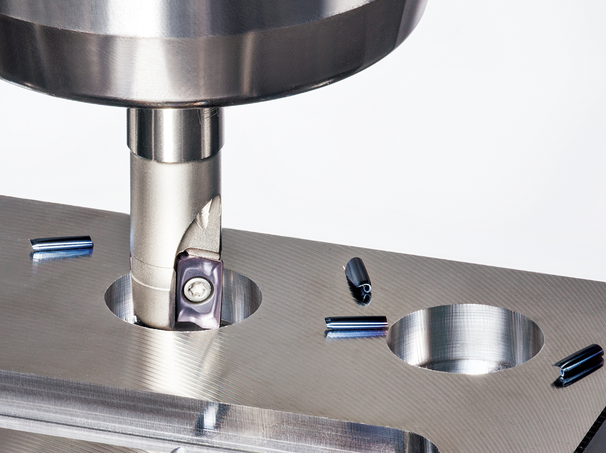
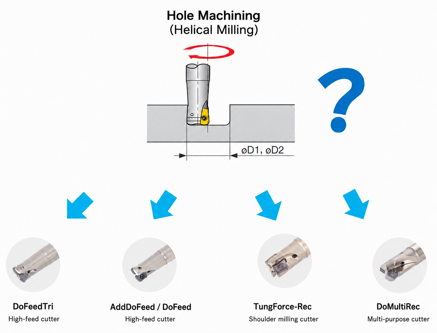
Helical milling is a machining method in which the tool follows circular interpolation while feeding in the Z direction at the same time. Instead of plunging straight down, the tool moves downward little by little while drawing a circle, creating a helical tool path.
This method is used for holemaking, pocket-entry machining, counterboring, and opening holes without a pilot hole. It makes it easier to machine hole diameters larger than the cutter diameter, and the same cutter can often be used for multiple hole sizes.
However, in helical milling the tool is always entering the workpiece at an inclined angle. Unlike ordinary side milling or slotting, you need to check the ramping angle, helical pitch, tool-center path, and feed correction.
Helical milling combines circular interpolation and Z-axis feed
The main checks are whether the tool supports helical milling, whether the ramping angle is appropriate, whether the pitch is not too large, and whether feed correction is handled correctly.
2. Three Key Values in Helical Milling
When setting helical milling conditions, start with the following three values.
| Item | Symbol | Description |
|---|---|---|
| Hole diameter | Dh | Target hole diameter or helical hole diameter |
| Cutter diameter | Dc | Diameter of the milling cutter used |
| Helical pitch | Ph | Z-axis movement per one tool revolution |
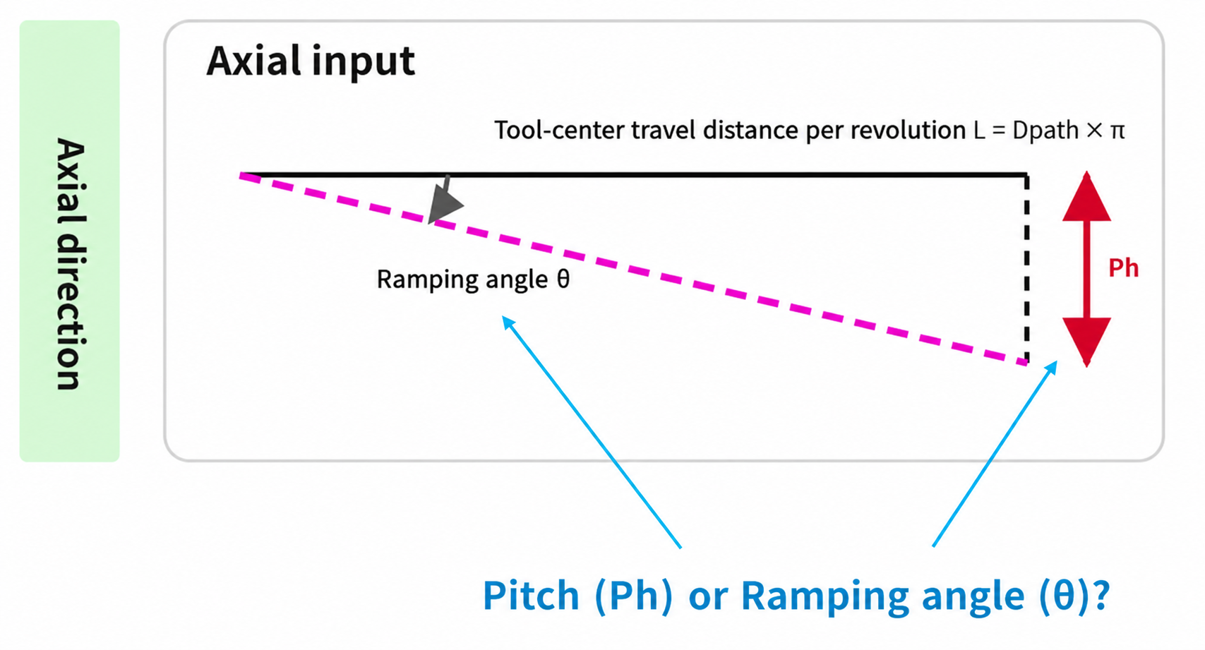
Once these three values are set, the tool-center path diameter and the tool-center travel distance per revolution can be determined.
Tool-center path diameter = Dh - Dc
Tool-center travel distance per revolution = (Dh - Dc) x pi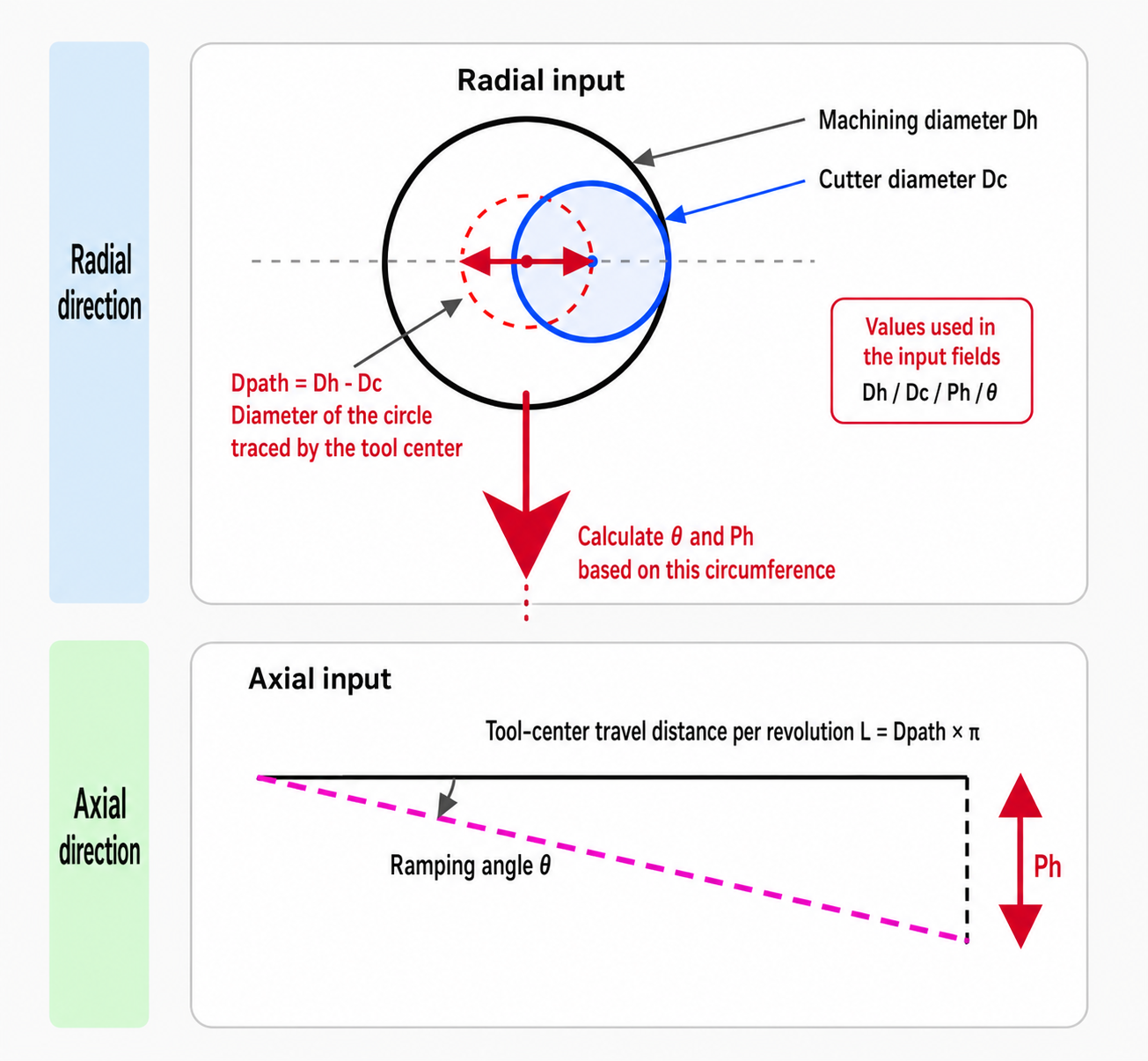
How to Think About Ramping Angle
Once the helical pitch is set, the ramping angle can be calculated.
Ramping angle = atan(helical pitch / tool-center travel distance per revolution)For example, when the hole diameter is 50 mm, the cutter diameter is 10 mm, and the helical pitch is 5 mm:
Tool-center path diameter = 50.0 - 10.0 = 40.0 mm
Tool-center travel distance per revolution = 40.0 x pi = 125.7 mm
Ramping angle = atan(5.0 / 125.7) = approx. 2.3 deg
If you want to set the ramping angle first, calculate the helical pitch with the following formula.
Helical pitch = tool-center travel distance per revolution x tan(ramping angle)The calculation basis is the tool-center path diameter, not the hole diameter itself
In helical milling calculations, it is important to use the diameter of the path drawn by the tool center, not the hole diameter itself.
3. Tool-Selection Points for Helical Milling
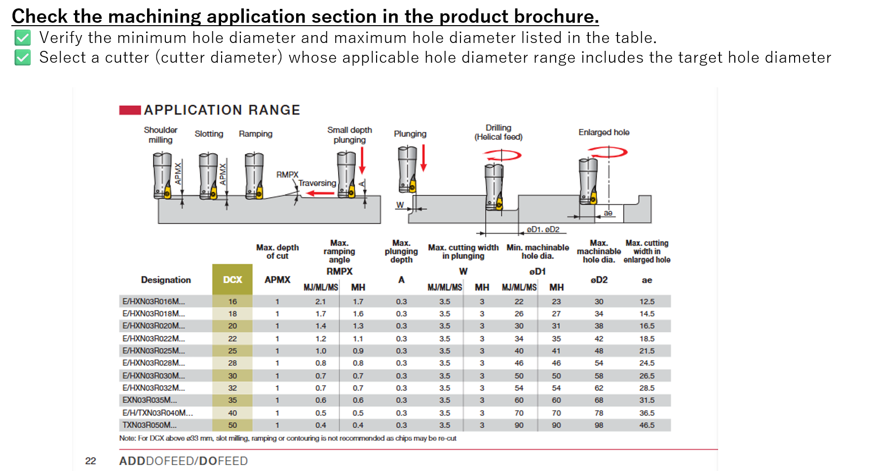
In helical milling, any cutter that fits inside the hole diameter is not automatically suitable. You need to confirm whether the tool supports helical milling, whether the hole diameter is within the minimum and maximum supported helical-hole range, and whether the pitch and ramping angle are within the tool specifications.
Types of Cutters Used for Helical Milling
The main candidates are shoulder milling cutters with ramping capability and high-feed cutters with ramping capability. For both types, confirm whether the tool can be used for helical milling, what the maximum ramping angle is, and whether the target diameter falls within the minimum and maximum helical-hole range.
For Roughing, High-Feed Cutters Are Usually the First Choice
When helical milling is used as a roughing process, it is reasonable to start by considering a high-feed cutter. Although high-feed cutters may have a smaller maximum depth of cut APMX, they can often apply a higher feed rate, which is advantageous for productivity.
Depending on the machining distance and tool-center path diameter, the maximum ramping angle of a shoulder cutter can become the limiting factor, preventing the cutter from fully using its available APMX. Therefore, a high-feed cutter can be advantageous even when its APMX is smaller, because it can apply higher feed conditions.
When to Start with a High-Feed Cutter
- Roughing: For productivity-focused machining, start with a high-feed cutter.
- Deep holes: High-feed cutters tend to resist chatter during long overhang machining and provide good chip evacuation.
- When shortening machining time is important: Even with smaller APMX, high-feed conditions can be applied more easily.
- Hard or difficult-to-cut materials: A low entering angle can thin the chip and reduce tool load.
How to Compare with Shoulder Milling Cutters
- Shoulder milling cutter: Even when APMX is large, the maximum ramping-angle limit may prevent full use of that capability.
- High-feed cutter: Even with smaller APMX, high-feed conditions can make it advantageous in roughing.
Where Shoulder Milling Cutters Are Effective
There are also cases where shoulder milling cutters are advantageous. Consider a shoulder cutter when workpiece rigidity is low or when the appearance of the machined hole wall is important.
| Situation suited to shoulder cutters | Reason |
|---|---|
| Low workpiece rigidity | Shoulder cutters can help reduce the radial component of cutting force and suppress the force pushing the workpiece. |
| Better hole-wall appearance is required | High-feed cutters may leave a scale-like surface on the hole wall. If wall finish is important, a shoulder cutter can be a better candidate. |
Use high-feed cutters as the roughing baseline; consider shoulder cutters for low-rigidity workpieces or better wall appearance
In actual selection, always check not only cutter type but also each tool's maximum ramping angle, minimum and maximum helical-hole diameter, APMX, and compatible inserts.
| Check item | Why it matters | Risk if ignored |
|---|---|---|
| Does the tool support helical milling? | Tool geometry, edge strength, and chip evacuation must be suitable. | Chipping, chatter, chip clogging |
| Is the diameter within the min/max helical-hole range? | Confirm that the tool can cover the target hole diameter. | Tool interference, excessive load |
| Is the pitch within APMX? | Confirm that the Z-axis depth per revolution is within tool specifications. | Edge breakage, poor surface quality |
| Is the ramping angle within the limit? | Confirm that the tool load during inclined entry remains acceptable. | Chipping, chatter, overload |
| Can the tool-center path be secured? | Confirm that the cutter diameter is not too close to the hole diameter. | Ramping angle tends to become too large |
| Is machining depth and overhang acceptable? | Avoid tool or holder interference. | Holder interference, insufficient rigidity |
| Are grade and chipbreaker suitable for the material? | The cutting edge must match the work material. | Wear, chipping, built-up edge |
| Is chip evacuation secured? | Chips have limited escape space inside a hole. | Chip recutting, tool damage |
| Is the condition within machine capability? | Check spindle speed, feed, and spindle power. | Unstable machining, inability to reach conditions |
Check hole diameter, cutter diameter, APMX, and maximum ramping angle together
For helical-milling tool selection, check the hole diameter, cutter diameter, minimum and maximum helical-hole diameter, APMX, and maximum ramping angle as one set.
4. Tool-Selection Procedure
This section outlines the practical flow for selecting a milling cutter for helical milling. First, set the candidate cutter diameter and confirm whether the tool can cover the target hole diameter. Then the flow branches depending on whether you decide the helical pitch first or the ramping angle first.
- Set the cutter diameter: Set the cutter diameter or candidate tool diameter.
- Temporarily select a tool from the min/max helical-hole range: Confirm whether the target diameter is within the tool's applicable range.
- Calculate the tool-center path diameter and travel distance: Once the cutter diameter is set, the basis for ramping-angle and pitch calculation is fixed.
- Choose whether pitch or ramping angle comes first: Either approach is possible; in the end, confirm both APMX and maximum ramping angle.
| Method | Value decided first | Value calculated next | Main checks |
|---|---|---|---|
| Method 1 | Helical pitch | Ramping angle | APMX and maximum ramping angle |
| Method 2 | Ramping angle | Helical pitch | Maximum ramping angle and APMX |
Method 1. Decide the Helical Pitch First
When deciding the helical pitch first, check whether the pitch exceeds the tool's APMX. If it is acceptable, apply that pitch and calculate the ramping angle from the tool-center travel distance and pitch.
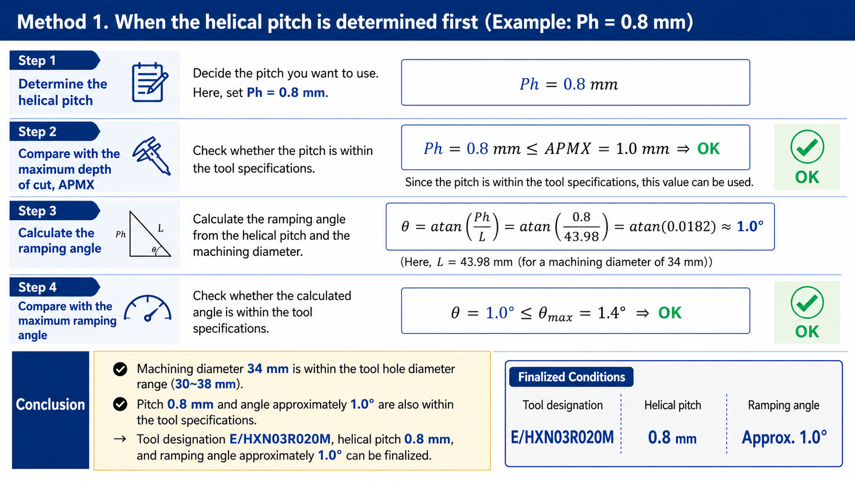
Ramping angle = atan(helical pitch / tool-center travel distance per revolution)Finally, confirm that the calculated ramping angle is within the candidate tool's maximum ramping angle. If there is no issue, the cutter diameter, tool item, helical pitch, and ramping angle can be finalized.
Method 2. Decide the Ramping Angle First
When deciding the ramping angle first, check whether the angle exceeds the candidate tool's maximum ramping angle. If it is acceptable, apply that ramping angle and calculate the helical pitch from the tool-center travel distance and ramping angle.
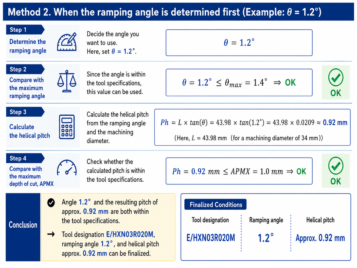
Helical pitch = tool-center travel distance per revolution x tan(ramping angle)Finally, confirm that the calculated helical pitch is within the candidate tool's APMX. If there is no issue, the cutter diameter, tool item, ramping angle, and helical pitch can be finalized.
The final checks are the same whether you start from pitch or angle
Confirm that the condition is within APMX, within the maximum ramping angle, and inside the tool's min/max helical-hole range.
5. Cautions During Helical Milling
Because the tool enters at an angle while moving along a circular path, helical milling requires more condition checks than ordinary side milling. In particular, always check ramping angle, pitch, feed correction, and chip evacuation.
Do Not Make the Ramping Angle Too Large
As the ramping angle increases, the load on the cutter shoulder and insert increases. Even when the angle is within the maximum ramping-angle limit, chatter or chipping can occur depending on work material, machine rigidity, and overhang length.
Keep the Helical Pitch Within APMX
Helical pitch is the amount of Z-axis depth per revolution. If the pitch is too large, it may exceed the tool's APMX and lead to chip clogging or chatter.
Be Careful: Tool-Center Travel and Cutting-Edge Travel Are Different
In helical milling, NC commands are based on the tool-center path. However, the actual cutting occurs at the tool periphery.
In internal helical milling, the tool-center path diameter is smaller than the machined hole diameter. Therefore, the travel distance of the tool center and the travel distance of the cutting edge are not the same.
If catalog feed values are commanded directly as tool-center feed, the actual feed at the cutting edge may become larger than expected. Check the tool-center command feed and feed correction so that the feed at the cutting edge does not become excessive.
Tool-center command feed = uncorrected feed x (Dh - Dc) / DhNote: Depending on the machine, CNC control, or CAM system, circular-feed correction may be handled automatically. Confirm the control specifications of the machine used for the actual program.
Secure Chip Evacuation
When helical milling inside a hole, chips have limited escape space. Chip clogging can lead to chipping, poor surface quality, abnormal noise, and chatter.
Calculated values are a guide for checking feasibility
Finalize cutting conditions after confirming tool specifications, work material, machine rigidity, workholding rigidity, and coolant conditions.
6. A Convenient Calculator for Pitch and Ramping Angle
As described above, helical milling requires checking the hole diameter, cutter diameter, pitch, ramping angle, and feed correction in sequence.
The formulas themselves are not difficult, but doing the calculations manually every time is time-consuming. If APMX or maximum ramping angle checks are missed, the condition may exceed the tool specifications.
For this reason, using a calculator that automatically calculates ramping angle and pitch is an efficient way to review helical milling conditions. The calculator below can switch between pitch-to-angle and angle-to-pitch calculation modes.
Helical Milling Calculator
Ramping Angle and Pitch Calculator
Check hole diameter, cutter diameter, pitch, ramping angle, and feed correction together.
Calculation Results
CalculatingMachining Depth

- Required revolutions
- --
- Programmed revolutions
- --
- Depth-fit pitch
- --
- Depth-fit angle
- --
Distance and Time
- 3D travel per revolution
- --
- Approx. total travel
- --
- Approx. machining time
- --
Judgement and Cautions
7. Introduction to the Tool Selector
After calculating ramping angle and helical pitch, the next question is which cutters can be used under those conditions. In helical milling, the hole diameter, cutter diameter, APMX, maximum ramping angle, and min/max helical-hole range must be checked together, which can make catalog-based searching time-consuming.
To support this check, a separate tool selector is available for finding candidate Tungaloy cutters from your input conditions. By narrowing down candidate cutters in the tool selector, you can review helical milling conditions more smoothly.
Use the calculator and tool selector for different roles
Use the calculator to check ramping angle, pitch, feed correction, and machining distance. Use the tool selector to find Tungaloy cutter candidates that match those conditions.
Note: The tool selector helps you check Tungaloy cutter candidates that match your input conditions.
Summary
Helical milling is a machining method in which the tool follows circular interpolation while feeding in the Z direction. It is useful for large holes that are difficult to machine with drills and for pocket-entry machining, but incorrect condition setting can increase tool load significantly.
- In helical milling, check hole diameter Dh, cutter diameter Dc, and tool-center path diameter.
- Calculate helical pitch and ramping angle based on the tool-center travel distance.
- For tool selection, always check min/max helical-hole diameter, APMX, and maximum ramping angle.
- Whether you start from pitch or angle, confirm that the final condition is within tool specifications.
- Because tool-center travel and cutting-edge travel are different, pay attention to feed correction.
- If manual calculation is troublesome, use the calculator to check conditions.
- Use the separate tool selector to check candidate tools.
In helical milling, calculations and tool selection should not be considered separately. It is important to check hole diameter, cutter diameter, pitch, ramping angle, feed correction, and tool specifications as one continuous workflow.