Fundamentals of Chipbreakers — From Basic Theory to Selection
When people hear the word “chipbreaker,” many may imagine a groove designed to break chips.
In practice, however, a chipbreaker refers to the entire set of cutting edge specifications, including the rake angle, land, and honing.
It is a key element for process stability, responsible not only for chip control but also for controlling cutting resistance and ensuring cutting edge strength at the same time.
This article systematically explains everything from the principles of chipbreakers to selection methods, considerations by workpiece material, and troubleshooting.
What you will learn in this article
- What is a chipbreaker? — Definition as cutting edge specifications
- Why are chipbreakers necessary?
- When no chipbreaker is the better choice
- How chips break: the principle
- What is the ideal chip shape?
- Basic criteria for selecting a chipbreaker
- Differences between finishing, medium-cutting, and roughing chipbreakers
- Chipbreakers work in combination with cutting conditions
- Considerations by workpiece material (ISO P/M/K/N/S/H)
- Review points when things do not work well
- Summary
1. What is a chipbreaker?
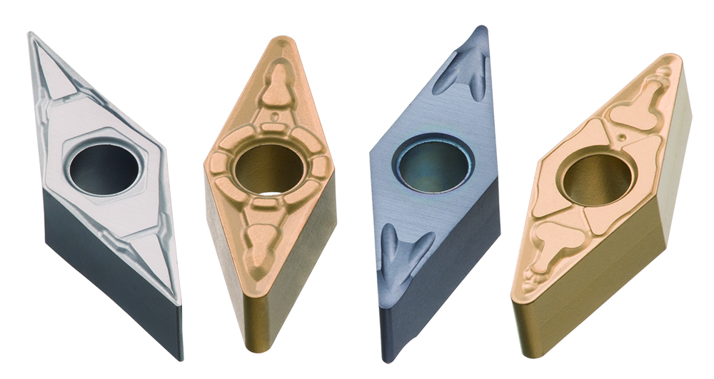
In a narrow sense, the term chipbreaker refers to the groove or protruding geometry provided on the rake face of an insert to break chips.
In actual insert design, however, a chipbreaker refers to the entire set of cutting edge specifications, including not only chip breaking but also cutting resistance control and cutting edge strength. This article explains chipbreakers based on this broader definition.
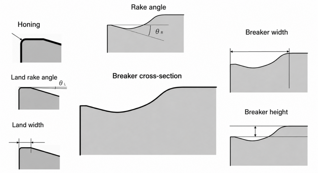
Elements that make up a chipbreaker
- Breaker width — Groove width that determines the distance over which chips curl
- Breaker wall height — Height of the wall that receives and bends the chip
- Rake angle — Angle that affects chip flow direction and cutting resistance
- Land width — Width of the flat area immediately behind the cutting edge
- Land rake angle — Inclination angle of the land surface.
- Honing (edge preparation) — Slight rounding applied to the cutting edge
Relationship between parameter factors and their effects
The table below summarizes how changes in each element affect three factors: “chip breaking performance,” “cutting resistance,” and “cutting edge strength.”
| Parameter factor | Direction of change | Chip breaking performance | Cutting resistance | Cutting edge strength |
|---|---|---|---|---|
| Breaker width | Make narrower | ↑ Easier to break chips | ↑ Increases | – |
| Breaker wall height | Make higher | ↑ Easier to break chips | ↑ Slightly increases | – |
| Rake angle | Increase positive angle | ↑ Easier to curl | ↓ Decreases | ↓ Decreases |
| Land width | Make wider | ↓ Slightly worsens | ↑ Increases | ↑ Improves |
| Land rake angle | Increase negative angle | ↓ Slightly worsens | ↑ Increases | ↑ Improves |
| Honing | Make larger | ↓ Slightly worsens | ↑ Increases | ↑ Improves |
POINT
“Selecting a chipbreaker” is equivalent to selecting the overall balance of these cutting edge specifications
Chip breaking performance, cutting resistance, and cutting edge strength are in a trade-off relationship, so it is important to find the optimum balance for the machining objective.
2. Why are chipbreakers necessary?
Problems when there is no chipbreaker
- Long continuous chips → chips wrapping around the workpiece or tool
- Risk of scratched machined surfaces and machine stoppage
- Operator safety concerns, as long chips are sharp and dangerous
- Especially in automatic machines and continuous machining, poor chip evacuation can directly lead to process stoppage
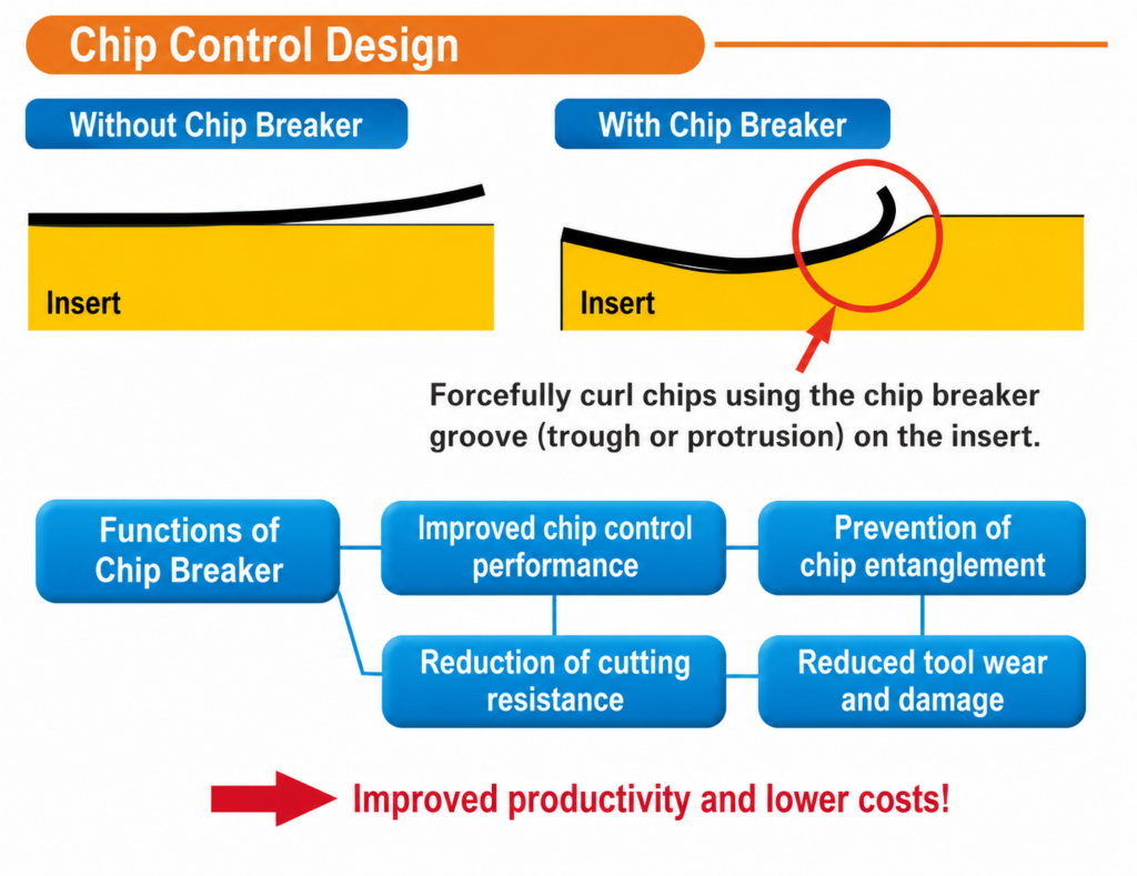
Advantages of having a chipbreaker
- Improved machining efficiency — Chips are properly broken and evacuated
- Longer tool life — Prevents abnormal loads caused by chip entanglement
- Stable machining quality — Reduces chip contact that can impair surface finish
More than chip control — three roles
A chipbreaker is responsible not only for chip control but also for controlling cutting resistance and ensuring cutting edge strength at the same time.
- Chip control — Properly breaks and evacuates chips through the design of breaker width and wall height
- Cutting resistance — Reduces resistance through the design of rake angle and breaker width, contributing to energy savings and chatter suppression
- Cutting edge strength — Ensures cutting edge strength through the design of land width, land rake angle, and honing, preventing fracture and abnormal wear
POINT
A chipbreaker is an element that simultaneously designs “chip control,” “cutting resistance,” and “cutting edge strength”
Selecting a breaker means choosing the optimum balance of these three factors. Looking only at chip control can lead to incorrect selection.
3. When no chipbreaker is the better choice
A chipbreaker is not “always necessary,” nor is it true that “the stronger it works, the better.” Depending on the machining objective, workpiece material, and cutting conditions, cases exist where no breaker or a breaker with a weak breaking effect is more advantageous.
■ When selecting a flat top
Workpiece materials whose chips naturally break short, such as cast iron and brass
Because the breaker’s chip-breaking function is unnecessary, a flat top can be used to prioritize cutting edge strength.
Extremely heavy cutting or interrupted cutting
Since a breaker groove can become a weak point in cutting edge strength, selecting a flat top can reduce the risk of fracture.
■ When selecting a breaker with a weak breaking effect
When you want to reduce cutting resistance
A breaker that restricts the chip increases resistance. When low resistance is prioritized over chip control, choosing a breaker with weak chip restraint is effective for suppressing resistance.
When you want to achieve excellent machined surface quality
When chip breaking is emphasized, chip restraint by the breaker increases chip thickness, creating chips that are more likely to scratch the machined wall. A breaker with weak restraint can generate chips that are less likely to damage the machined surface, allowing surface quality to be prioritized.
POINT
Depending on the machining objective, workpiece material, and conditions, “no breaker” or a “weak breaker” can also be the right choice
It is important to avoid the assumption that a breaker is always required and to make decisions suited to the machining objective.
4. How chips break: the principle
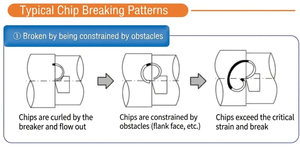
The principle by which a chipbreaker breaks chips can be understood in the following four steps.
- Being sheared and lifted — The chip begins to flow along the rake face from the cutting edge
- Curling — The chip is forced to curl strongly by the breaker geometry, such as the groove and wall
- Strain increases — The curl radius becomes smaller, increasing bending strain inside the chip
- Breaking — The chip breaks when strain exceeds its limit
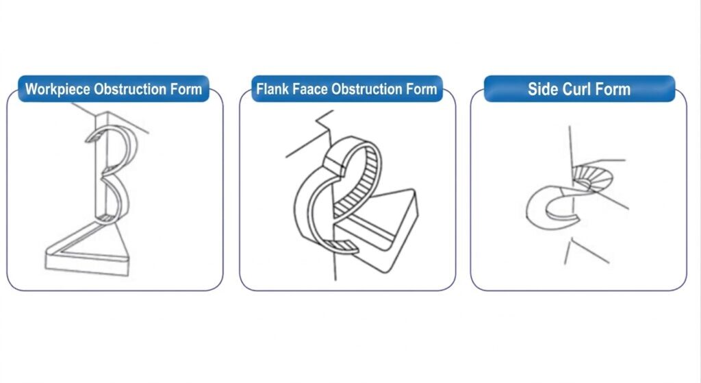
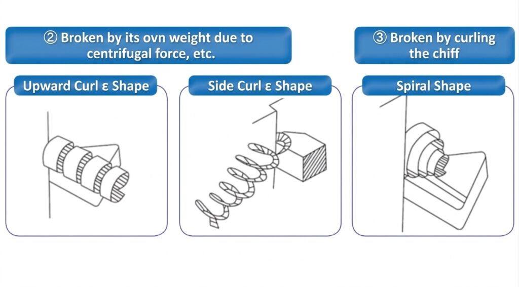
Three chip-breaking patterns
- Breaking against the tool — The curled chip collides with the breaker wall or insert face and breaks
- Breaking against the workpiece — The curled chip hits the workpiece surface and breaks
- Self-breaking type — The chip breaks naturally only by its own bending strain
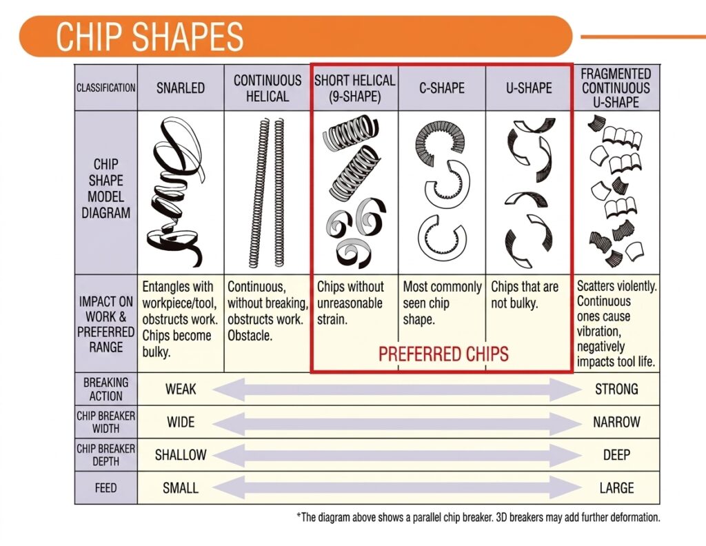
5. What is the ideal chip shape?
Knowing “what kind of chip is good” provides a basis for judging breaker selection and condition adjustment.
Ideal chips
- Coiled chips with a few turns — Moderately curled and naturally broken
- Moderately broken C-shaped chips — Not too short and not too long, easy to evacuate
Undesirable chips
❌ Excessively long continuous chips
These wrap around the workpiece or tool and scratch the machined surface. In automatic machines, they can cause process stoppage due to poor evacuation.
❌ Extremely fine and hard chips
This indicates that the breaker is restraining the chip too strongly. It increases load on the cutting edge, leading to shorter tool life and a higher risk of fracture.
POINT
The ideal chip is “not too short, not too long, and easy to evacuate”
The goal is not simply to break chips; balance is important.
6. Basic criteria for selecting a chipbreaker
There are three main basic criteria to consider when selecting a chipbreaker.
① Machining area
This refers to the categories of finishing, medium cutting, and roughing. Because the required sharpness, cutting edge strength, and chip control capability differ, select a breaker system suited to the machining area.
② Workpiece material
Chip formation varies greatly depending on the workpiece material, such as steel, stainless steel, cast iron, non-ferrous metals, and heat-resistant alloys. Each manufacturer provides breaker systems corresponding to ISO classifications (P/M/K/N/S/H).
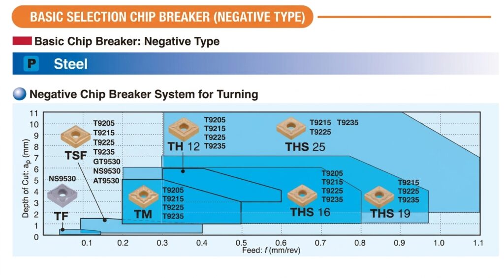
③ Depth of cut (ap) and feed (f) range
Each breaker has its own suitable range of depth of cut and feed. Use the chipbreaker selection map (ap × f) shown in catalogs to select a breaker that matches the machining conditions.
POINT
How to read a chipbreaker selection map
The horizontal axis shows feed (f), the vertical axis shows depth of cut (ap), and the applicable range of each breaker is indicated as an area. Check which area your machining conditions fall into and select the corresponding breaker.
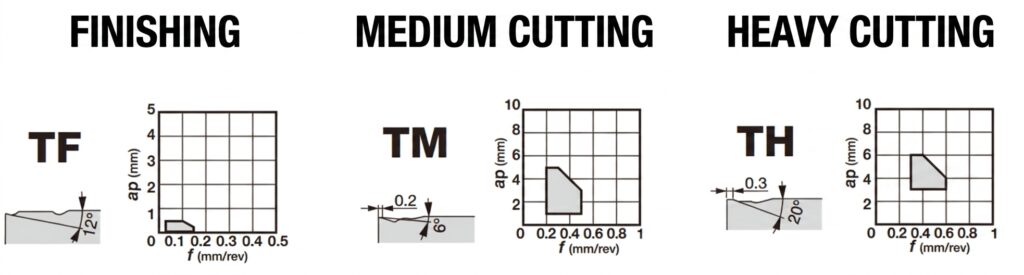
7. Differences between finishing, medium-cutting, and roughing chipbreakers
The performance required of a breaker varies greatly depending on the machining area.
| Item | For finishing | For medium cutting | For roughing |
|---|---|---|---|
| Feed and depth of cut | Low feed, shallow depth of cut | Medium range | High feed, deep depth of cut |
| Sharpness | Sharp (low resistance) | Balanced type | Strength-oriented |
| Cutting edge strength | Lower | Medium | High |
| Surface quality | ◎ Advantageous | ○ Good | △ Disadvantageous |
| Chip control | Supports thin chips | Supports a wide range of conditions | Powerfully breaks thick chips |
| Application range | Narrow (limited conditions) | Wide (first choice for mass production) | Suitable for heavy and interrupted cutting |
Finishing chipbreakers
Designed with an emphasis on sharpness in low-feed and shallow-depth-of-cut ranges. They are advantageous for surface quality and keep cutting resistance low. However, cutting edge strength may be insufficient under rough conditions or interrupted cutting.
Medium-cutting chipbreakers
These are the most versatile and are designed to easily cover a wide range of conditions. In mass-production sites, they are often the first choice; when in doubt, trying a medium-cutting breaker first is the standard approach.
Roughing chipbreakers
Robust designs that support deep depths of cut, high feeds, and heavy cutting. They bend chips strongly and provide high cutting edge strength, but may be disadvantageous in terms of low resistance and finished surface quality.
8. Chipbreakers work in combination with cutting conditions
Chipbreaker selection is not completed by breaker geometry alone. The way it works changes depending on the combination with machining conditions.
Machining conditions that affect breaker performance
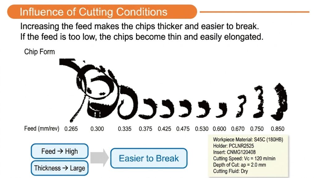
- Feed (f) — If the feed is too low, chips become thin and difficult to break. If it is too high, excessive restraint increases cutting edge load.
- Depth of cut (ap) — If it is too shallow, chip width becomes insufficient and the breaker is less effective.
- Cutting speed (Vc) — In general, as cutting speed increases, the effective range of the breaker tends to become narrower.
- Coolant — The effective range changes depending on the presence or absence of cutting fluid and the supply method. High-pressure coolant assists chip evacuation and breaking.
- Holder angle (approach angle) — Changes chip flow direction, thickness, and width, affecting how the breaker works.
POINT
Breaker selection is not completed by the breaker alone
It is determined by the combination of feed, depth of cut, speed, and coolant. In general, as cutting speed increases, chip temperature rises and the chip becomes softer, so the feed and depth-of-cut range in which the breaker is effective becomes narrower.
9. Considerations by workpiece material
Chip formation differs greatly depending on the type of workpiece material, and the characteristics required of a chipbreaker also change. The key points for each material group are summarized below according to ISO workpiece material classifications (P/M/K/N/S/H).
ISO P Steel (carbon steel and alloy steel)
- A representative material for which breakers are easy to apply. Under appropriate conditions, it is relatively easy to achieve the target chip shape.
- In general, chip control is good and cutting force is within a stable range.
- Low-carbon steel (C<0.25%) is ductile and prone to adhesion, including built-up edge. A sharp cutting edge and positive rake angle are effective. Keeping the depth of cut at or above the nose radius improves chip control.
- In high-alloy steels and high-hardness steels, heat generation increases and the effective range of the breaker tends to become narrower.
ISO M Stainless steel
- A representative material that tends to produce long chips and is difficult to control.
- Austenitic stainless steel is prone to work hardening, producing hard chips and built-up edge. A sharp cutting edge and positive geometry are recommended.
- Duplex stainless steel has high tensile strength and large cutting forces. Chips become thick and hard, creating a risk of chip hammering, or cutting edge damage caused by chip impact.
- A combination of dedicated breaker systems for finishing, medium cutting, and roughing with high-pressure coolant is effective.
- It is important to cut below the work-hardened layer and keep the depth of cut constant.
ISO K Cast iron
- Characterized by short chips that break easily; chip control is generally good.
- Gray cast iron (GCI) has high self-breaking properties and chips tend to break short. Resistance to abrasive wear is more important than the breaker’s chip-breaking function.
- Nodular cast iron (NCI) tends to produce built-up edge, and in soft ferritic grades, adhesive wear is dominant.
- CGI (compacted graphite iron) has tensile strength 2 to 3 times higher than GCI, resulting in higher cutting force and heat generation.
- ADI (austempered ductile iron) reduces tool life by 40 to 50% compared with NCI. Attention must be paid to high dynamic cutting forces.
- Negative inserts that emphasize cutting edge strength are frequently used.
ISO N Non-ferrous metals (aluminum, copper alloys, etc.)
- Aluminum alloys have low cutting forces and tend to produce long chips. If alloyed, chip control is relatively easy.
- Pure aluminum has high adhesion, making a sharp cutting edge and high cutting speed essential.
- Aluminum with a Si content of 13% or higher is highly abrasive, and PCD tools are effective.
- Copper alloys such as brass and bronze generate relatively short chips. Free-cutting copper alloys have low dependence on breakers.
- In general, sharp cutting edges and positive geometry are basic requirements. Breakers with weak breaking effect are also an option when sharpness is prioritized.
ISO S Heat-resistant superalloys and titanium (HRSA)
Nickel-based alloys, such as Inconel
- High-temperature strength is high, and segmented chips that are difficult to break are generated.
- High dynamic cutting forces create heavy load on the cutting edge. Watch for notch wear and built-up edge.
- Round inserts with a large approach angle and positive geometry are recommended.
Titanium alloys
- Thermal conductivity is low, so cutting heat concentrates at the cutting edge.
- Thin chips contact a narrow area of the rake face, creating concentrated load near the cutting edge.
- If cutting speed is too high, chemical reactions with the tool material may create a risk of sudden fracture.
- A sharp and tough cutting edge is required.
Cobalt-based alloys
- Among the most difficult-to-machine materials, with high hot corrosion resistance. Specific cutting resistance is extremely high at 2700 to 3100 N/mm².
Common points
- The combination of high-pressure coolant and dedicated breakers is essential.
- Chip control in low-speed and low-feed ranges is a challenge.
- Machinability varies greatly between annealed and age-hardened materials, so confirm the heat treatment condition before selecting a breaker.
ISO H Hardened steel (50 to 68 HRc)
- Mainly used in finishing operations. Specific cutting resistance is high at 2550 to 4870 N/mm², but chip control is relatively good.
- CBN tools are mainstream, and 3D chipbreakers can improve chip control, provide rake angle, and suppress chatter.
- Plastic deformation caused by high cutting temperature and resistance to abrasive wear are important issues.
10. Review points when things do not work well
The table below summarizes typical symptoms, main causes, and countermeasures when chip-related problems occur.
| Symptom | Main causes | Countermeasures |
|---|---|---|
| Long chips are produced | Insufficient feed / insufficient depth of cut / nose radius too large / inappropriate entering angle (approach angle) | Increase feed / increase depth of cut / reduce nose radius / review the approach angle |
| Chips are too short and hard, causing high cutting edge load | Excessive feed / nose radius too small / breaker restraint too strong, meaning incorrect breaker selection | Reduce feed / change to a breaker for high-feed applications / consider a breaker with weaker breaking effect |
| Poor machined surface quality | Chips hit and scratch the workpiece surface / chip thickness increases due to breaker restraint / built-up edge | Review breaker and cutting conditions / change to a breaker with weaker restraint / increase cutting speed to suppress built-up edge |
💡 Common misconceptions
| Misconception | Reality |
|---|---|
| Changing the breaker solves everything | It will not work unless feed, depth of cut, speed, coolant, and holder angle are also appropriate. |
| The finer the chips are broken, the better | If chips are too fine, cutting edge load increases, causing shorter tool life and fracture. |
| Only surface quality needs to be checked | Chips may hit the workpiece surface and cause scratches. Chip shape also needs to be checked. |
Summary — Key points for chipbreaker selection
A chipbreaker is not simply a “groove that breaks chips”; it refers to the entire set of cutting edge specifications, including rake angle, land, and honing. It is a key element for process stability that simultaneously affects chip control, cutting resistance, and cutting edge strength.
- Geometry selection and condition optimization work as a set — Changing only the breaker will not produce the desired effect if the conditions are unsuitable.
- Use the chipbreaker selection map — Check the breaker suited to the machining conditions using catalog maps by P/M/K/N/S/H classification.
- Consider workpiece material characteristics — Because chip formation differs by material, select a breaker system suited to the workpiece material.
- “None” or “weak” can also be correct — Depending on the machining objective, a flat top or a breaker with weak restraint can also be an effective option.
- Check chip shape — The ideal is a shape that is “not too short, not too long, and easy to evacuate.” Observe chips after machining and use them as clues for improvement.
CONCLUSION
Selecting the optimum breaker according to workpiece material characteristics and machining conditions is the key to manufacturing high-quality products
By correctly understanding chipbreakers and optimizing the balance between “chip control,” “cutting resistance,” and “cutting edge strength,” both machining quality and productivity can be achieved.