

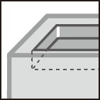
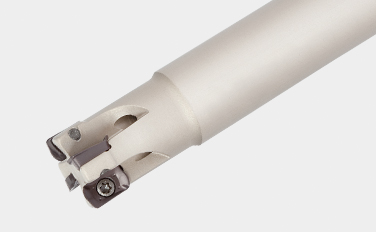
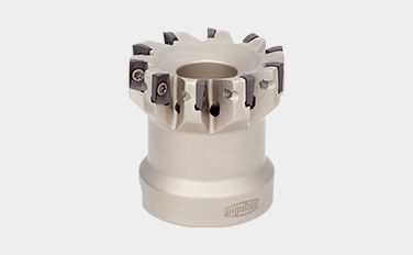
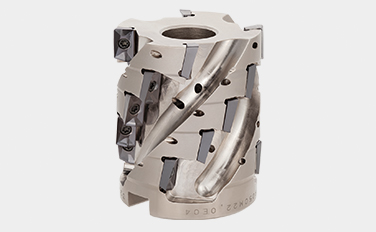
Excellent surface finish and wall accuracy in shoulder milling
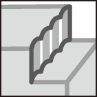
Helical cutting edge and large axial rake angle on insert provide smooth cutting in semi-finishing operation

Applications & Features
Applications


Features
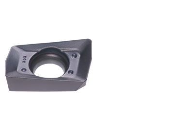
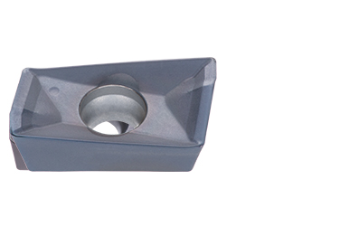
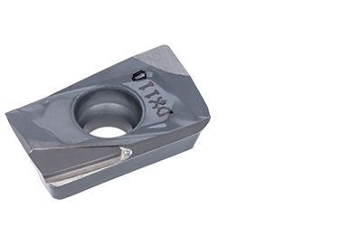
1. Inserts
• Helical cutting edge for high wall accuracy.
• Wiper edge for excellent surface finish.
• Optimized rake angle for sharpness and reliability.
• 4 chipbreaker types for a wide range of applications.
• Corner radius range up to 3.2 mm (0.126″).
• Available in DLC coating and cermet inserts.
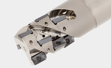
2. Cutter body
• Air holes for improved chip evacuation.
• Available in coarse- and close-pitch, and long shank cutters.
Inserts & Grades
Inserts
AO*T07/18
- Maximum depth of cut
– AO*T07: 7 mm
– AO*T18: 16.7 mm
AS*T11
- Maximum depth of cut: 10.6 mm
ASGW11
- Maximum depth of cut: 4.5 mm
Main Grades
AH3225
![]()
![]()
-
Good balance between wear and fracture resistance
-
Suitable for steel and stainless steel
T1215
![]()
-
Good balance between wear and chipping resistance
-
Suitable for milling cast iron
DX110
![]()
-
Excellent sharpness for high surface quality
-
Suitable for fi nishing non-ferrous metal and nonmetal
Cutter bodies
Shank Type
EPO (ø12 – ø63mm)
High precision shoulder square endmills
- EPO07
– Tool dia.: ø12 – ø28 mm
– Insert: AO*T07 - EPO11
– Tool dia.: ø12 – ø50 mm
– Insert: AS*T11 / ASGW11 - EPO18
– Tool dia.: ø25 – ø63 mm
– Insert: AO*T18
Modular Type
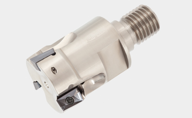
HPO (ø12 – ø32mm)
High precision shoulder square endmills (TungRec) with TungFlex
- HPO07
– Tool dia.: ø12 – ø25 mm
– Insert: AO*T07 - HPO11
– Tool dia.: ø20 – ø32 mm
– Insert: AS*T11 / ASGW11
Bore Type
TPO (ø32 – ø160 mm)
High precision shoulder square mills
- TPO07
– Tool dia.: ø32 – ø50mm
– Insert: AO*T07 - TPO11
– Tool dia.: ø40 – 100 mm
– Insert: AS*T11 / ASGW11 - TPO18
– Tool dia.: ø40 – ø160mm
– Insert: AO*T18
Bore Type
TLS11 (ø50mm)
Highly productive shoulder square mills for roughing
– Insert: AS*T11
Practical examples
Example #1
General Engineering
| Part: | Machine parts |
| Material: | SCM440 / 42CrMo4 |
| Cutter: | TPO07R040M16.0E10 (ø40, z = 10) |
| Insert: | AOMT070208PDPR-MJ |
| Grade: | AH725 |
| Cutting conditions: | Vc = 130 (m/min) fz = 0.1 (mm/t) Vf = 1000 (mm/min) ap = 3.0 (mm) ae = ~ 30 (mm) Application: Shoulder milling Coolant: Dry Machine: Vertical MC, BT40 |

Example #2
General Engineering
| Part: | Compressor parts |
| Material: | SS400 / E275A |
| Cutter: | EPS11033RSB (ø33, z = 5) |
| Insert: | ASMT11T304PDPR-MJ |
| Grade: | NS740 |
| Cutting conditions: | Vc = 150 (m/min) fz = 0.13 (mm/t) Vf = 940 (mm/min) ap = 5 (mm) ae = 15 (mm) Application: Shoulder milling Coolant: Dry Machine: Vertical MC, BT50 |

Example #3
General Engineering
| Part: | Machine parts |
| Material: | SS400 / E275A |
| Cutter: | TLS11R050M22.0E04 |
| Insert: | ASMT11T308PDPR-MJ |
| Grade: | AH725 |
| Cutting conditions: | Vc = 150 (m/min) fz = 0.17 (mm/t) Vf = 649 (mm/min) ap = 40 (mm) ae = 5 (mm) Application: Shoulder milling Coolant: Dry Machine: Vertical MC, BT50 |

Standard cutting conditions
TPO07 / EPO07 / HPO07
| ISO | Workpiece material | Hardness HB |
Grade | Cutting speed Vc (m/min) |
Feed per tooth: fz (mm/t) | ||
|---|---|---|---|---|---|---|---|
| MJ | HJ | AJ | |||||
| Low carbon steel S15C, etc. C15E4, etc. |
< 200 | AH725 | 90 – 200 | 0.05 – 0.1 | 0.4 – 0.9 | – | |
| High carbon steel and alloy steel S55C, SCM440, etc. C55, 42CrMo4, etc. |
200 – 300 | AH725 | 90 – 150 | 0.05 – 0.1 | 0.4 – 0.9 | – | |
| Tool steel SKD11, etc. X153CrMoV12, etc. |
150 – 300 | AH725 | 80 – 120 | 0.05 – 0.1 | 0.4 – 0.9 | – | |
| Stainless steel SUS304, etc. X5CrNi18-9, etc. |
– | AH140 | 90 – 150 | 0.05 – 0.1 | 0.4 – 0.9 | – | |
| Grey cast irons FC250, etc. 250, etc. |
150 – 250 | AH725 | 100 – 180 | 0.05 – 0.1 | 0.4 – 0.9 | – | |
| Ductile cast irons FCD450, etc. 450-10S, etc. |
150 – 250 | AH725 | 80 – 150 | 0.05 – 0.1 | 0.4 – 0.9 | – | |
| Aluminium alloys Si < 13% |
– | KS15F | 300 – 1000 | – | – | 0.08 – 0.2 | |
| Aluminium alloys Si ≥ 13% |
– | KS15F | 100 – 200 | – | – | 0.08 – 0.2 | |
| Titanium alloys Ti-6Al-4V, etc. |
– | AH725 | 20 – 50 | 0.05 – 0.1 | 0.4 – 0.9 | – | |
| Superalloys Inconel 718, etc. |
– | AH725 | 20 – 35 | 0.05 – 0.08 | 0.2 – 0.6 | – | |
- To remove excessive chip accumulation use an air blast.
- To avoid build up edge on the cutting edges (aluminium machining), use a water soluble coolant.
- When cutting an interrupted surface or a casted skin, the feed per tooth (fz) should be reduced to the lower recommended value shown in the above table.
- Cutting conditions are limited by machine power, workpiece rigidity, and spindle output. When the cutting width, depth, or overhang length is large, set Vc and fz to the lower recommended values and check the machine power and vibration.
TPO11 / EPO11 / HPO11
| ISO | Workpiece material | Hardness HB |
Priority | Grade | Cutting speed Vc (m/min) |
Feed per tooth: fz (mm/t) | ||||
|---|---|---|---|---|---|---|---|---|---|---|
| MJ | MS | AJ | – | |||||||
| Low carbon steel S15C, etc. C15E4, etc. |
< 200 | First choice | AH3225 | 100 – 250 | 0.1 – 0.2 | – | – | – | ||
| < 200 | For wear resistance | T3225 | 100 – 250 | 0.1 – 0.2 | – | – | – | |||
| < 200 | Surface quality | NS740 | 100 – 250 | 0.05 – 0.15 | – | – | – | |||
| High carbon steel, Alloy steel S45C, SCM440, etc. C45, 42CrMo4, etc. |
200 – 300 | First choice | AH3225 | 100 – 200 | 0.1 – 0.15 | – | – | – | ||
| 200 – 300 | For wear resistance | T3225 | 100 – 200 | 0.1 – 0.15 | – | – | – | |||
| 200 – 300 | Surface quality | NS740 | 100 – 200 | 0.05 – 0.12 | – | – | – | |||
| Tool steel SKD61, etc. X40CrMoV5-1, etc. |
150 – 300 | First choice | AH3225 | 100 – 150 | 0.1 – 0.15 | – | – | – | ||
| 150 – 300 | For wear resistance | T3225 | 100 – 150 | 0.1 – 0.15 | – | – | – | |||
| Stainless steel SUS304, etc. X5CrNi18-9, etc. |
– | First choice | AH3225 | 80 – 200 | – | 0.08 – 0.2 | – | – | ||
| – | For wear resistance | AH130 | 80 – 200 | – | 0.08 – 0.2 | – | – | |||
| Grey cast irons FC250, etc. 250, etc. |
150 – 250 | First choice | AH120 | 100 – 250 | 0.12 – 0.2 | – | – | – | ||
| 150 – 250 | For wear resistance | T1215 | 100 – 250 | 0.12 – 0.2 | – | – | – | |||
| Ductile cast irons FCD450, etc. 400-15S, etc. |
150 – 250 | First choice | AH120 | 80 – 200 | 0.12 – 0.2 | – | – | – | ||
| 150 – 250 | For wear resistance | T1215 | 80 – 200 | 0.12 – 0.2 | – | – | – | |||
| Aluminium alloys Si < 13% |
– | First choice | DS1100 | 300 – 1000 | – | – | 0.05 – 0.2 | – | ||
| – | For wear resistance | DX110 | 500 – 2,000 | – | – | – | 0.05 – 0.2 | |||
| Aluminium alloys Si ≥ 13% |
– | First choice | DS1100 | 100 – 200 | – | – | 0.05 – 0.2 | – | ||
| – | For wear resistance | DX110 | 200 – 800 | – | – | – | 0.05 – 0.2 | |||
| Copper alloys | – | First choice | KS05F | 200 – 500 | – | – | 0.05 – 0.2 | – | ||
| – | For wear resistance | DX110 | 200 – 500 | – | – | – | 0.05 – 0.2 | |||
| Titanium alloys Ti-6Al-4V, etc. |
– | First choice | AH130 | 20 – 60 | 0.08 – 0.13 | – | – | – | ||
| – | For fracture resistance | AH3225 | 20 – 60 | 0.08 – 0.13 | – | – | – | |||
| Superalloys Inconel718, etc. |
– | First choice | AH725 | 20 – 40 | 0.08 – 0.13 | – | – | – | ||
| – | For fracture resistance | AH130 | 20 – 40 | 0.08 – 0.13 | – | – | – | |||
| – | For wear resistance | AH120 | 20 – 40 | 0.08 – 0.13 | – | – | – | |||
| Hardened steel |
SKD61, etc. X40CrMoV5-1, etc. |
40 – 50 HRC | First choice | AH725 | 45 – 70 | 0.04 – 0.08 | – | – | – | |
| SKD11, etc. X153CrMoV12, etc. |
50- 60 HRC | First choice | AH725 | 40 – 65 | 0.04 – 0.06 | – | – | – | ||
TLS11 / ELS11
| ISO | Workpiece material | Hardness HB |
Priority | Grade | Cutting speed Vc (m/min) |
Feed per tooth: fz (mm/t) | ||
|---|---|---|---|---|---|---|---|---|
| MJ | MS | AJ | ||||||
| Low carbon steel S15C, etc. C15E4, etc. |
< 200 | First choice | AH3225 | 100 – 250 | 0.10 – 0.18 | – | – | |
| < 200 | For wear resistance | T3225 | 100 – 250 | 0.10 – 0.18 | – | – | ||
| High carbon steel, Alloy steel S45C, SCM440, etc. C45, 42CrMo4, etc. |
200 – 300 | First choice | AH3225 | 100 – 200 | 0.08 – 0.14 | – | – | |
| 200 – 300 | For wear resistance | T3225 | 100 – 200 | 0.08 – 0.14 | – | – | ||
| Tool steel SKD61, etc. X40CrMoV5-1, etc. |
150 – 300 | First choice | AH3225 | 100 – 200 | 0.08 – 0.14 | – | – | |
| 150 – 300 | For wear resistance | T3225 | 100 – 200 | 0.08 – 0.14 | – | – | ||
| Stainless steel SUS304, etc. X5CrNi18-9, etc. |
– | First choice | AH3225 | 100 – 150 | – | 0.08 – 0.15 | – | |
| – | For wear resistance | AH130 | 100 – 150 | – | 0.08 – 0.15 | – | ||
| Grey cast irons FC250, etc. 250, etc. |
150 – 250 | First choice | AH120 | 100 – 250 | 0.10 – 0.18 | – | – | |
| 150 – 250 | For wear resistance | T1215 | 100 – 250 | 0.10 – 0.18 | – | – | ||
| Ductile cast irons FCD450, etc. 400-15S, etc. |
150 – 250 | First choice | AH120 | 80 – 200 | 0.10 – 0.18 | – | – | |
| 150 – 250 | For wear resistance | T1215 | 80 – 200 | 0.10 – 0.18 | – | – | ||
| Aluminium alloys Si < 13% |
– | First choice | DS1100 | 200 – 500 | – | – | 0.05 – 0.18 | |
| Aluminium alloys Si ≥ 13% |
– | First choice | DS1100 | 100 – 200 | – | – | 0.05 – 0.18 | |
| Titanium alloys Ti-6AI-4V, etc. |
– | First choice | AH130 | 20 – 60 | – | 0.08 – 0.14 | – | |
| – | For fracture resistance | AH3225 | 20 – 60 | – | 0.08 – 0.14 | – | ||
| Superalloys Inconel718, etc. |
– | First choice | AH725 | 20 – 40 | 0.06 – 0.12 | – | – | |
| – | For wear resistance | AH130 | 20 – 40 | 0.06 – 0.12 | – | – | ||
| – | For wear resistance | AH3225 | 20 – 40 | 0.06 – 0.12 | – | – | ||
- To remove excessive chip accumulation use an air blast.
- To avoid build up edge on the cutting edges (aluminium machining), use a water soluble coolant.
- When cutting an interrupted surface or a casted skin, the feed per tooth (fz) should be reduced to the lower recommended value shown in the above table.
- Cutting conditions are limited by machine power, workpiece rigidity, and spindle output. When the cutting width, depth, or overhang length is large, set Vc and fz to the lower recommended values and check the machine power and vibration.
TPO18 / EPO18
| ISO | Workpiece material | Brinell hardness HB | Priority | Cutting speed Vc (m/min) | fz (mm/t) | |
|---|---|---|---|---|---|---|
| MJ | AJ | |||||
| Low carbon steel S15C, etc. C15E4, etc. | – 200 | AH725 | 100 – 250 | 0.08 – 0.25 | – | |
| High carbon steel and alloy steel S55C, SCM440, etc. C55, 42CrMo4, etc. | 200 – 300 | AH725 | 100 – 230 | 0.08 – 0.2 | – | |
| Tool steel SKD11, etc. X153CrMoV12, etc. | 150 – 300 | AH725 | 100 – 180 | 0.08 – 0.2 | – | |
| Stainless steel SUS304, etc. X5CrNi18-9, etc. | – | AH140 | 90 – 200 | 0.08 – 0.2 | – | |
| Grey cast irons FC250, etc. 250, etc. | 150 – 250 | AH725 | 140 – 250 | 0.08 – 0.25 | – | |
| Ductile cast irons FCD450, etc. 450-10S, etc. | 150 – 250 | AH725 | 110 – 200 | 0.08 – 0.25 | – | |
| Aluminium alloys Si < 13% | – | KS15F | 300 – 1000 | – | 0.05 – 0.25 | |
| Aluminium alloys Si ≥ 13% | – | KS15F | 100 – 200 | – | 0.05 – 0.25 | |
| Titanium alloys Ti-6AI-4V, etc. | – | AH725 | 20 – 60 | 0.08 – 0.18 | – | |
| Superalloys Inconel718, etc. | – | AH725 | 20 – 40 | 0.08 – 0.15 | – | |
- To remove excessive chip accumulation use an air blast.
- To avoid build up edge on the cutting edges (aluminium machining), use a water soluble coolant.
- When cutting an interrupted surface or a casted skin, the feed per tooth (fz) should be reduced to the lower recommended value shown in the above table.
- Cutting conditions are limited by machine power, workpiece rigidity, and spindle output. When the cutting width, depth, or overhang length is large, set Vc and fz to the lower recommended values and check the machine power and vibration.
For more information about this product, visit our online e-catalog or download the product report:

Industries |
|
Industries Learn more |

e-Catalog |
|
e-Catalog Learn more |
Resources
 Tungaloy APP
 TUNG NaviTool recommendations for your specific needs
 Machine Power Calculator
 Turning Insert Selection Guide
 Tungaloy Success ReportExplore Tungaloy’s TSR for custom machining insights with easy search
 Technical GuidesAccess Tungaloy’s technical guides for valuable insights, references, and resources.
 MatrixTool management system
 Special tool drawing generatorQuickly generate simple drawings for special products.