

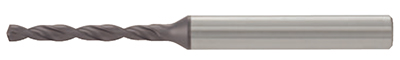
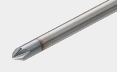
Coated solid carbide drill for excellent stability
Ideal combination of drill geometry and carbide composition for exceptional performance on a wide range of drilling applications

Applications & Features
Applications

Features for DSW
1. New coated grade with highly improved wear resistance
• New coated carbide grade with a high level of versatility. Perfect grade for stable and long tool life on a wide range of materials.
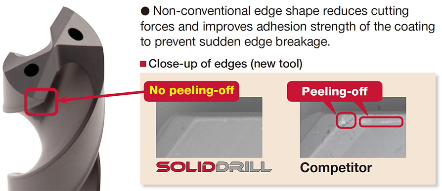
2. Innovative cutting edge offers reliable drilling
• Non-conventional edge shape reduces cutting forces and improves adhesion strength of the coating to prevent sudden edge breakage.
3. World-wide standard shank style – Standardized with DIN6535-Form HA
• Only 6 shank size diameters available – ø6, ø8, ø10, ø12, ø14, ø16 mm. This reduces the number of collets required.
Features for DSM
1. Variety of dimensions and L/D
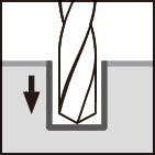
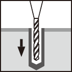
• Allows deep hole drilling up to 5 to 15 times the drill diameter.
• Available as standard items from ø0.1 to ø3.0 mm in 0.01 mm increments. Shank diameters are all unified to ø3 mm.
2. Center drills for machining guide hole
• DSM-CP140 type has a 140° point angle which can effectively prevent the cutting edge from chipping.
• DSM-CP90 type, which has a 90° point angle, can be also used for chamfering of the hole mouth.
Drill bodies & Grades
Drill bodies
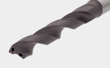
DSW-DI (ø3 – ø12 mm)
- With coolant hole type
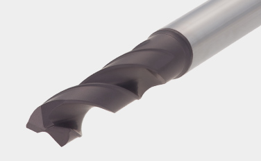
DSW-DE (ø3 – ø12 mm)
- Without coolant hole. Economical type
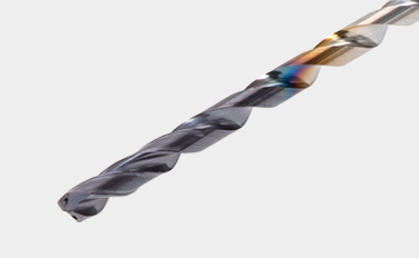
DSW-CI (ø3 – ø10 mm)
- Cylindrical shank, with coolant holes
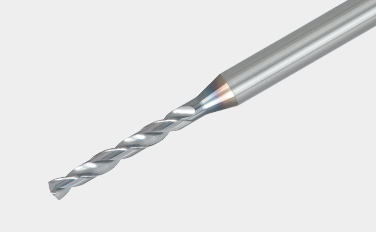
DSM (ø0.1 – ø3 mm)
- Small dia. solid carbide drill, L/D (ULDR) = 5 – 15
DSM-CP (ø3 mm)
- Drills for center hole
Main Grades
AH725
![]()
![]()
![]()
![]()
- P15 – P30 / M15 – M30 / K25 – K30 / S15 – S25
- Good balance between wear and chipping resistance
- Suitable for machining steel and stainless steel under general cutting conditions
YH170
![]()
![]()
- P20 – P35 / M20 – M35
- High resistance to wear and fracture
- Designed for drilling carbon steel and stainless steel
YH180
![]()
![]()
- High wear resistance
- Designed for drilling carbon steel and stainless steel
Practical examples
Example #1
General Engineering
| Part: | Machine parts |
| Material: | C55 (ISO) |
| Drill body: | DSW103-040-12DE3 |
| Hole diameter: | øDc = 10.3 (mm) |
| Grade: | AH725 |
| Cutting conditions: | Vc = 50 (m/min) f = 0.3 (mm/rev) H = 24 (mm) Coolant: Wet (External) Machine: Horizontal MC |

Standard cutting conditions
DSW-DE (External supply)
| ISO | Workpiece material | Brinell hardness (HB) |
Cutting speedVc (m/min) | Feed: f (mm/rev) | ||||
|---|---|---|---|---|---|---|---|---|
| ø3 – ø6 | ø6 – ø10 | ø10 – ø16 | ø3 – ø6 | ø6 – ø10 | ø10 – ø12 | |||
 |
Low carbon steels (C < 0.3) SS400, SM490, S25C, etc. C15E4, E275A, E355D, etc. |
– 180 | 40 – 100 | 60 – 120 | 60 – 130 | 0.15 – 0.3 | 0.15 – 0.35 | 0.2 – 0.5 |
| Carbon steels (C > 0.3) S45C, S55C, , etc. C45, C55, etc. |
180 – 300 | 40 – 90 | 50 – 120 | 60 – 130 | 0.15 – 0.3 | 0.15 – 0.35 | 0.2 – 0.4 | |
| High alloy steels SCM440, etc. 42CrMo4, etc. |
250 – 350 | 40 – 80 | 50 – 100 | 50 – 100 | 0.1 – 0.2 | 0.15 – 0.3 | 0.15 – 0.35 | |
 |
Stainless steels SUS304, etc. X5CrNi18-9, etc. |
– 200 | 20 – 40 | 30 – 50 | 30 – 60 | 0.05 – 0.2 | 0.1 – 0.25 | 0.1 – 0.3 |
 |
Grey cast irons FC300, etc. 250, etc. |
– 200 | 40 – 90 | 50 – 95 | 50 – 100 | 0.15 – 0.3 | 0.2 – 0.4 | 0.2 – 0.5 |
| Ductile cast irons FCD450, etc. 450-10S, etc. |
– 300 | 30 – 80 | 40 – 90 | 45 – 90 | 0.1 – 0.3 | 0.2 – 0.4 | 0.2 – 0.4 | |
 |
Aluminium alloys ADC12, etc. AlSi11Cu3, etc. |
– | 40 – 90 | 50 – 100 | 50 – 100 | 0.15 – 0.3 | 0.2 – 0.4 | 0.2 – 0.5 |
 |
Titanium alloys Ti-6Al-4V, etc. |
– | 20 – 40 | 20 – 40 | 20 – 40 | 0.1 – 0.2 | 0.15 – 0.25 | 0.15 – 0.4 |
| Heat-resistant alloys, Inconel Inconel 718, etc. |
250 – | 10 – 30 | 10 – 30 | 10 – 30 | 0.03 – 0.07 | 0.05 – 0.1 | 0.07 – 0.12 | |
 |
High hardened steels SKD11, etc. X153CrMoV12, etc. |
– 40HRC | 20 – 40 | 20 – 40 | 20 – 40 | 0.05 – 0.15 | 0.05 – 0.15 | 0.05 – 0.2 |
- The cutting parameters shown in the table are merely a starting guideline for general machining. Values should be varied depending on the power or rigidity of the machine to be used. Optimum conditions should be selected depending on the actual chip control or damage on edges.
- When using the smaller diameter tools in each range, set the feed “f” to the lower recommended values.
- The coolant supply is critical for the provision of stable machining conditions and enhanced tool life. A large coolant volume should be supplied, especially when drilling difficult-to-cut materials.
- When drilling stainless steel with low machinability such as austenitic stainless steel with a depth deeper than L/D = 3, a pecking cycle or internal coolant supply is recommended.
DSW-DI (Internal supply)
| ISO | Workpiece material | Brinell hardness (HB) |
Cutting speedVc (m/min) | Feed: f (mm/rev) | ||||
|---|---|---|---|---|---|---|---|---|
| ø3 – ø6 | ø6 – ø10 | ø10 – ø16 | ø3 – ø6 | ø6 – ø10 | ø10 – ø12 | |||
|
Low carbon steels (C < 0.3) SS400, SM490, S25C, etc. C15E4, E275A, E355D, etc. |
– 180 | 70 – 140 | 80 – 160 | 90 – 190 | 0.15 – 0.3 | 0.15 – 0.35 | 0.2 – 0.5 |
| Carbon steels (C > 0.3) S45C, S55C, , etc. C45, C55, etc. |
180 – 300 | 50 – 130 | 70 – 160 | 80 – 170 | 0.15 – 0.3 | 0.15 – 0.35 | 0.2 – 0.4 | |
| High alloy steels SCM440, etc. 42CrMo4, etc. |
250 – 350 | 40 – 100 | 60 – 140 | 60 – 160 | 0.1 – 0.2 | 0.15 – 0.3 | 0.15 – 0.35 | |
|
Stainless steels SUS304, etc. X5CrNi18-9, etc. |
– 200 | 25 – 75 | 50 – 100 | 50 – 120 | 0.05 – 0.2 | 0.1 – 0.25 | 0.1 – 0.3 |
|
Grey cast irons FC300, etc. 250, etc. |
– 200 | 80 – 140 | 100 – 160 | 100 – 180 | 0.15 – 0.3 | 0.2 – 0.4 | 0.2 – 0.45 |
| Ductile cast irons FCD450, etc. 450-10S, etc. |
– 300 | 70 – 140 | 80 – 150 | 80 – 170 | 0.1 – 0.3 | 0.2 – 0.4 | 0.2 – 0.45 | |
|
Aluminium alloys ADC12, etc. AlSi11Cu3, etc. |
– | 60 – 200 | 60 – 200 | 60 – 200 | 0.15 – 0.3 | 0.2 – 0.4 | 0.2 – 0.5 |
|
Titanium alloys Ti-6Al-4V, etc. |
– | 20 – 60 | 30 – 80 | 30 – 80 | 0.1 – 0.2 | 0.1 – 0.25 | 0.15 – 0.4 |
| Heat-resistant alloys, Inconel Inconel 718, etc. |
250 – | 10 – 30 | 10 – 40 | 10 – 40 | 0.03 – 0.07 | 0.05 – 0.1 | 0.07 – 0.15 | |
|
High hardened steels SKD11, etc. X153CrMoV12, etc. |
– 40HRC | 20 – 50 | 30 – 60 | 30 – 60 | 0.05 – 0.15 | 0.05 – 0.15 | 0.05 – 0.2 |
- The cutting parameters shown in the table are merely a starting guideline for general machining. Values should be varied depending on the power or rigidity of the machine to be used. Optimum conditions should be selected depending on the actual chip control or damage on edges.
- When using the smaller diameter tools in each range, set the feed “f” to the lower recommended values.
- Oil holes that become blocked may cause drill breakages. A fi lter to prevent the circulation of chips must be used on the coolant supply system.
DSW-CI (16xD, 20xD)
| ISO | Workpiece material | Cutting speed Vc (m/min) |
Feed: f (mm/rev) | ||
|---|---|---|---|---|---|
| Tool diameter: DC (mm) | |||||
| ø3 – ø5 | ø5.1 – ø8 | ø8.1 – ø10 | |||
|
Low carbon steels (C < 0.3) SS400, SM490, S25C, etc. C15E4, E275A, E355D, etc. |
70 – 90 | 0.1 – 0.18 | 0.1 – 0.2 | 0.1 – 0.25 |
| High carbon steels (C > 0.3) S45C, S55C, etc. C45, C55, etc. |
70 – 90 | 0.1 – 0.18 | 0.1 – 0.2 | 0.1 – 0.25 | |
| Low alloy steels SCM415, etc. 18CrMo4, etc. |
70 – 90 | 0.1 – 0.18 | 0.1 – 0.2 | 0.1 – 0.25 | |
| Alloy steels SCM440, SCr420, etc. 42CrMo4, 20Cr4, etc. |
75 – 85 | 0.08 – 0.14 | 0.08 – 0.18 | 0.12 – 0.2 | |
|
Stainless steels SUS304, SUS316, etc. X5CrNi18-9, X5CrNiMo17-12-2, etc. |
55 – 65 | 0.04 – 0.12 | 0.08 – 0.16 | 0.1 – 0.18 |
|
Grey cast irons FC250, etc. GG25, etc. |
80 – 100 | 0.14 – 0.24 | 0.16 – 0.26 | 0.18 – 0.3 |
| Ductile cast irons FCD700, etc. GGG70, etc. |
80 – 100 | 0.14 – 0.24 | 0.16 – 0.26 | 0.18 – 0.3 | |
|
Titanium alloys Ti-6Al-4V, etc. |
35 – 45 | 0.06 – 0.12 | 0.08 – 0.16 | 0.1 – 0.18 |
| Nickel-based alloys | 30 – 40 | 0.06 – 0.12 | 0.08 – 0.16 | 0.1 – 0.18 | |
DSW-CI (30xD)
| ISO | Workpiece material | Cutting speed Vc (m/min) |
Feed: f (mm/rev) | ||
|---|---|---|---|---|---|
| Tool diameter: DC (mm) | |||||
| ø3 – ø5 | ø5.1 – ø8 | ø8.1 – ø10 | |||
|
Low carbon steels (C < 0.3) SS400, SM490, S25C, etc. C15E4, E275A, E355D, etc. |
70 – 90 | 0.08 – 0.11 | 0.12 – 0.17 | 0.1 – 0.22 |
| High carbon steels (C > 0.3) S45C, S55C, etc. C45, C55, etc. |
70 – 90 | 0.08 – 0.11 | 0.12 – 0.17 | 0.1 – 0.22 | |
| Low alloy steels SCM415, etc. 18CrMo4, etc. |
70 – 90 | 0.08 – 0.11 | 0.12 – 0.17 | 0.1 – 0.22 | |
| Alloy steels SCM440, SCr420, etc. 42CrMo4, 20Cr4, etc. |
75 – 85 | 0.06 – 0.09 | 0.08 – 0.14 | 0.1 – 0.18 | |
|
Stainless steels SUS304, SUS316, etc. X5CrNi18-9, X5CrNiMo17-12-2, etc. |
55 – 65 | 0.04 – 0.1 | 0.08 – 0.14 | 0.1 – 0.16 |
|
Grey cast irons FC250, etc. GG25, etc. |
80 – 100 | 0.14 – 0.22 | 0.16 – 0.26 | 0.18 – 0.25 |
| Ductile cast irons FCD700, etc. GGG70, etc. |
80 – 100 | 0.14 – 0.22 | 0.16 – 0.24 | 0.18 – 0.25 | |
|
Titanium alloys Ti-6Al-4V, etc. |
35 – 45 | 0.06 – 0.1 | 0.08 – 0.12 | 0.1 – 0.13 |
| Nickel-based alloys | 30 – 40 | 0.06 – 0.1 | 0.08 – 0.12 | 0.08 – 0.13 | |
DSM
| ISO | Workpiece material | Hardness | Cutting speedVc (m/min) | Feed: f (mm/rev) | ||||||
|---|---|---|---|---|---|---|---|---|---|---|
| ø0.1 – ø0.3 | ø0.31 – ø0.5 | ø0.51 – ø3 | ø0.1 – ø0.3 | ø0.31 – ø0.5 | ø0.51 – ø1 | ø1.01 – ø2 | ø2.01 – ø3 | |||
|
Carbon steels, Alloy steels |
– 300HB | 5 – 20 | 15 – 30 | 25 – 60 | 0.001 – 0.004 | 0.002 – 0.01 | 0.005 – 0.05 | 0.03 – 0.09 | 0.05 – 0.1 |
|
Stainless steels | – 200HB | 2 – 12 | 6 – 18 | 10 – 20 | 0.0005 – 0.004 | 0.002 – 0.008 | 0.005 – 0.03 | 0.01 – 0.04 | 0.02 – 0.05 |
|
Grey cast irons | 150 – 250HB | 5 – 15 | 10 – 25 | 20 – 50 | 0.0005 – 0.004 | 0.002 – 0.012 | 0.005 – 0.03 | 0.01 – 0.06 | 0.03 – 0.12 |
| Ductile cast irons | 150 – 250HB | 5 – 15 | 10 – 25 | 20 – 50 | 0.001 – 0.003 | 0.002 – 0.01 | 0.005 – 0.02 | 0.01 – 0.05 | 0.03 – 0.1 | |
|
Aluminium alloys | – | 10 – 20 | 10 – 30 | 20 – 50 | 0.001 – 0.01 | 0.005 – 0.03 | 0.01 – 0.05 | 0.04 – 0.15 | 0.06 – 0.2 |
| Copper / Brass | – | 10 – 20 | 10 – 30 | 20 – 50 | 0.001 – 0.01 | 0.005 – 0.03 | 0.01 – 0.05 | 0.04 – 0.15 | 0.06 – 0.2 | |
|
Heat-resistant alloys | – 40HRC | 2 – 6 | 5 – 10 | 8 – 20 | 0.0005 – 0.003 | 0.002 – 0.004 | 0.002 – 0.004 | 0.002 – 0.004 | ※ |
|
High hardened steels | – 50HRC | 4 – 8 | 6 – 10 | 6 – 16 | 0.0005 – 0.002 | 0.001 – 0.005 | 0.005 – 0.02 | 0.01 – 0.03 | 0.02 – 0.06 |
※ Not recommended
- When the drilling depth is deeper than L/D = 5, use drill pecking every 10 to 50% of the drill diameter.
- The above cutting conditions are applied to when a water soluble cutting fluid is used. For drilling a hole smaller than ø0. 3 mm, use of a starting drill is recommended.
- When setting the drill, the drill runout should be within 0.002 mm on the taper. (Especially for the drill diameter smaller than ø0.5 mm)
DSM-CP
| ISO | Workpiece material | Hardness | Cutting speedVc (m/min) | Feed: f (mm/rev) | |
|---|---|---|---|---|---|
| DSM-CP90 | DSM-CP140 | ||||
|
Carbon, Mild and Alloy steels | – 300HB | 30 – 80 | 0.01 – 0.06 | 0.03 – 0.08 |
|
Stainless steels | – 200HB | 15 – 40 | 0.01 – 0.03 | 0.02 – 0.06 |
|
Grey and ductile cast irons | 150 – 250HB | 30 – 80 | 0.02 – 0.06 | 0.05 – 0.1 |
|
Aluminium alloys | – | 60 – 120 | 0.02 – 0.1 | 0.05 – 0.15 |
|
High hardened steels | – 45HRC | 10 – 40 | ※ | 0.01 – 0.05 |
※ Not recommended
- Use DSM-CP140 for drilling hard materials and stainless steel that have work-hardening characteristic.
- The above cutting conditions are designed when using water-soluble cutting fluid, in which case, set the cutting speed to the lower side of the range.
For more information about this product, visit our online e-catalog or download the product
report:
e-Catalog
Metric
SolidDrill
GigaMiniDrill
Imperial
SolidDrill
GigaMiniDrill

Recursos
 Tungaloy APP
 TUNG NaviRecomendaciones de herramientas para sus necesidades específicas
 Machine Power Calculator
 Turning Insert Selection Guide
 Tungaloy Success ReportExplore Tungaloy’s TSR for custom machining insights with easy search
 Technical GuidesAccess Tungaloy’s technical guides for valuable insights, references, and resources.
 MatrixSistema de gestión de herramientas