

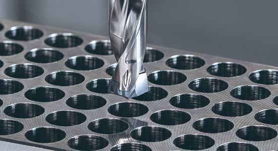
The best solution for steel and cast iron milling
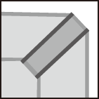
Exact simulation analysis provides light weight cutter with low cutting

Applications & Features
Applications


Features
1. CBN grade inserts for high-speed cast iron machining
High CBN content grade composed of extremely dense medium CBN grains

Inserts & Grades
Inserts
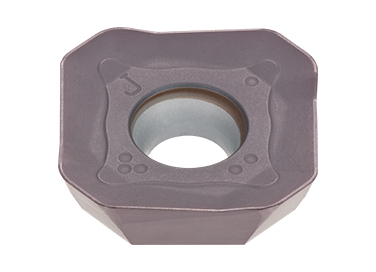
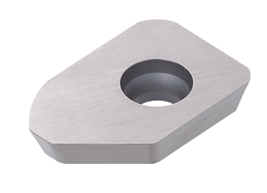
F2-SWGW
- Maximum depth of cut: 0.5 mm
WSGW
- Wiper edge
SW*T1304
- Maximum depth of cut: 10 mm
Grades
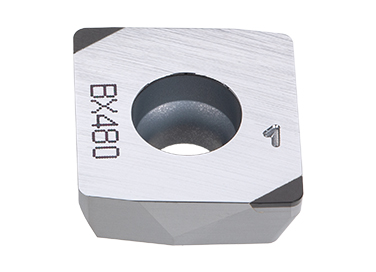
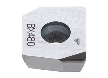
BX480
![]()
- Hardest CBN
- Ideal for ferrous sintered metal
- Suitable for high-speed face milling of cast iron
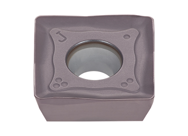
AH130
![]()
- High chipping and fracture resistance
- Designed for machining austenitic stainless steel under general cutting conditions
AH3135
![]()
- High fracture resistance
- Suitable for machining steel and stainless steel under general cutting conditions
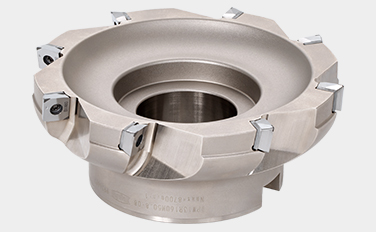
Cutter bodies
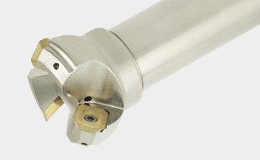
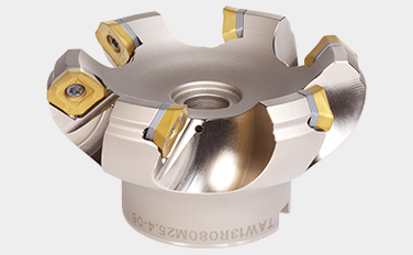
Shank Type
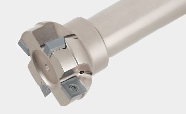
EPW13 (ø32 – ø80mm)
Square shoulder endmill, shank type, with screw clamp system
Practical examples
Example #1
| Part: | Cylinder block |
| Material: | FC250 / 250 |
| Cutter: | TPW13R125M38.1-08 (DCX = 125 mm, CICT = 8) |
| Insert: | 2-SWGW130508PDLSR x6, WSGW130508PDLSR x2 |
| Grade: | BX480 |
| Cutting conditions: | Vc = 800 (m/min) fz = 0.11 (mm/t) Vf = 1,760 (mm/min) ap = 0.2 (mm) ae = ~ 80 (mm) Application: Face milling Coolant: Dry Machine: Horizontal M/C, KM100 |

Example #2
| Part: | Cylinder block |
| Material: | FC250 / 250 |
| Cutter: | TPW13 cutter (customized, DCX = 250 mm, CICT = 12) |
| Insert: | 2-SWGW130508PDLSR x10, WSGW130508PDLSR x2 |
| Grade: | BX480 |
| Cutting conditions: | Vc = 1,178 ~ 1,257 (m/min) fz = 0.05 ~ 0.11 (mm/t) Vf = 900 ~ 1,980 (mm/min) ap = 0.2 (mm) ae = ~ 200 (mm) Application: Face milling Coolant: Dry Machine: Horizontal M/C, KM100 |

Example #3
| Part: | Hydraulic part |
| Material: | Chromium molybdenum steel (SCM415) |
| Cutter: | TPW13R080M25.4-04 (ø80, z=4) |
| Insert: | SWMT1304PDPR-MS |
| Grade: | AH140 |
| Cutting conditions: | Vc = 120 (m/min) fz = 0.18 (mm/t) Vf = 350 (mm/min) ap = 1.2 (mm) ae = ~ 50 (mm) Application: Face milling Coolant: Dry Machine: – |

Standard cutting conditions
TAW13, EAW13
| ISO | Workpiece materials |
Hardness | Priority | Grade | Cutting speed Vc(m/min) |
Roughing (Depth of cut ≥ 1.0 mm) | |||||
|---|---|---|---|---|---|---|---|---|---|---|---|
| Feed per tooth:fz (mm/t) | |||||||||||
| MJ | ML | HJ | MS | Flat top | AJ | ||||||
 |
Mild steel Low carbon steel |
< 180 HB | First choice | AH3225 (AH3135) |
100 – 270 | 0.05 – 0.3 | 0.05 – 0.25 | 0.2 – 0.6 | – | 0.05 – 0.3 | – |
| < 180 HB | Wear resistance | T3225 | 150 – 300 | 0.05 – 0.3 | – | 0.2 – 0.6 | – | 0.05 – 0.3 | – | ||
| < 180 HB | Surface quality | NS740 | 100 – 300 | 0.05 – 0.23 | – | – | – | 0.05 – 0.23 | – | ||
| Carbon steel Alloy steel |
< 300 HB | First choice | AH3225 (AH3135) |
100 – 230 | 0.05 – 0.25 | 0.05 – 0.2 | 0.2 – 0.5 | – | 0.05 – 0.25 | – | |
| < 300 HB | Wear resistance | T3225 | 150 – 280 | 0.05 – 0.25 | – | 0.2 – 0.5 | – | 0.05 – 0.25 | – | ||
| < 300 HB | Surface quality | NS740 | 100 – 230 | 0.05 – 0.2 | – | – | – | 0.05 – 0.2 | – | ||
| Die steel | < 30 HRC | First choice | AH3225 (AH3135) |
100 – 180 | 0.05 – 0.2 | 0.05 – 0.2 | 0.2 – 0.4 | – | 0.05 – 0.2 | – | |
| < 30 HRC | Wear resistance | T3225 | 100 – 180 | 0.05 – 0.2 | – | 0.2 – 0.4 | – | 0.05 – 0.2 | – | ||
 |
Stainless steel | < 250 HB | First choice | AH3135 | 80 – 200 | 0.1 – 0.25 | 0.1 – 0.2 | 0.2 – 0.5 | 0.1 – 0.2 | – | – |
| < 250 HB | Wear resistance | T3225 | 150 – 250 | 0.1 – 0.25 | 0.1 – 0.2 | 0.2 – 0.5 | – | 0.1 – 0.25 | – | ||
 |
Grey cast iron | 150 – 250 HB | First choice | AH8015 (AH120) |
150 – 250 | 0.05 – 0.25 | 0.05 – 0.2 | 0.2 – 0.6 | – | 0.05 – 0.25 | – |
| 150 – 250 HB | Wear resistance | T1215 | 180 – 300 | 0.05 – 0.25 | – | 0.2 – 0.6 | – | 0.05 – 0.25 | – | ||
| Ductile cast iron | 150 – 250 HB | First choice | AH8015 (AH120) |
100 – 180 | 0.05 – 0.25 | 0.05 – 0.2 | 0.2 – 0.6 | – | 0.05 – 0.25 | – | |
| 150 – 250 HB | Wear resistance | T1215 | 120 – 200 | 0.05 – 0.25 | – | 0.2 – 0.6 | – | 0.05 – 0.25 | – | ||
 |
Aluminium alloys Si < 13% |
– | First choice | DS2005 KS05F |
300 – 1000 | – | – | – | – | – | 0.05 – 0.2 |
| – | Wear resistance | DX140 | 200 – 800 | – | – | – | – | – | 0.05 – 0.2 | ||
| Aluminium alloys Si ≥ 13% |
– | First choice | DS2005 KS05F |
80 – 300 | – | – | – | – | – | 0.05 – 0.2 | |
| – | Wear resistance | DX140 | 200 – 800 | – | – | – | – | – | 0.05 – 0.2 | ||
| Copper alloys | – | First choice | DS2005 KS05F |
200 – 500 | – | – | – | – | – | 0.05 – 0.2 | |
| – | Wear resistance | DX140 | 200 – 800 | – | – | – | – | – | 0.05 – 0.2 | ||
 |
Titanium alloys Ti-6Al-4V, etc. |
– 40 HRC | First choice | AH130 | 30 – 60 | 0.1 – 0.25 | – | 0.2 – 0.5 | 0.1 – 0.2 | – | – |
| Heat-resistance alloys Inconel 718, etc. |
– 40 HRC | First choice | AH8015 (AH120) |
20 – 50 | 0.05 – 0.15 | – | 0.1 – 0.3 | – | – | – | |
 |
Hardened steel SKD61, etc. X40CrMoV5-1, etc. |
40 – 50HRC | First choice | AH8015 (AH120) |
45 – 70 | 0.08 – 0.15 | – | 0.1 – 0.3 | – | – | – |
– When using an aggressive depth of cut (for AP or AE), set the Vc and/or fz to the lower side of the value shown in the table.
– Dry cutting (or compressed air) is generally recommended. When excessive chip welding occurs on the cutting edge such as during stainless steel machining, use a water soluble cutting fluid and reduce Vc.
– When wet machining mild steel, carbon steel, or alloy steel, reduce the Vc and/or fz.
– Do not use TAW13 cutters for ramping, plunging, or drilling application as they are not designed for feeding in the Z axis direction.
| ISO | Workpiece materials |
Hardness | Priority | Grade | Cutting speed Vc (m/min) |
Light cutting to finishing (Depth of cut < 1.0 mm) | ||||||
|---|---|---|---|---|---|---|---|---|---|---|---|---|
| Feed per tooth:fz (mm/t) | ||||||||||||
| MJ | ML | HJ | MS | Flat top | AJ | |||||||
|
Mild steel Low carbon steel |
< 180 HB | First choice | AH3225 (AH3135) |
100 – 270 | 0.05 – 0.25 | 0.05 – 0.2 | 0.2 – 0.6 | – | 0.05 – 0.25 | – | |
| < 180 HB | Wear resistance | T3225 | 150 – 300 | 0.05 – 0.25 | – | 0.2 – 0.6 | – | 0.05 – 0.25 | – | |||
| < 180 HB | Surface quality | NS740 | 100 – 300 | 0.05 – 0.2 | – | – | – | 0.05 – 0.23 | – | |||
| Carbon steel Alloy steel |
< 300 HB | First choice | AH3225 (AH3135) |
100 – 230 | 0.05 – 0.2 | 0.05 – 0.25 | 0.2 – 0.5 | – | 0.05 – 0.2 | – | ||
| < 300 HB | Wear resistance | T3225 | 150 – 280 | 0.05 – 0.2 | – | 0.2 – 0.5 | – | 0.05 – 0.2 | – | |||
| < 300 HB | Surface quality | NS740 | 100 – 230 | 0.05 – 0.18 | – | – | – | 0.05 – 0.18 | – | |||
| Die steel | < 30 HRC | First choice | AH3225 (AH3135) |
100 – 180 | 0.05 – 0.18 | 0.05 – 0.12 | 0.2 – 0.4 | – | 0.05 – 0.18 | – | ||
| < 30 HRC | Wear resistance | T3225 | 100 – 180 | 0.05 – 0.18 | – | 0.2 – 0.4 | – | 0.05 – 0.18 | – | |||
|
Stainless steel | < 250 HB | First choice | AH3135 | 80 – 200 | 0.1 – 0.2 | 0.1 – 0.18 | 0.2 – 0.5 | 0.1 – 0.18 | – | – | |
| < 250 HB | Wear resistance | T3225 | 150 – 250 | 0.1 – 0.2 | 0.1 – 0.18 | 0.2 – 0.5 | – | 0.1 – 0.2 | – | |||
|
Grey cast iron | 150 – 250 HB | First choice | AH8015 (AH120) |
150 – 250 | 0.1 – 0.2 | 0.05 – 0.18 | 0.2 – 0.6 | – | 0.1 – 0.2 | – | |
| 150 – 250 HB | Wear resistance | T1215 | 180 – 300 | 0.1 – 0.2 | – | 0.2 – 0.6 | – | 0.1 – 0.2 | – | |||
| Ductile cast iron | 150 – 250 HB | First choice | AH8015 (AH120) |
100 – 180 | 0.1 – 0.2 | 0.05 – 0.18 | 0.2 – 0.6 | – | 0.1 – 0.2 | – | ||
| 150 – 250 HB | Wear resistance | T1215 | 120 – 200 | 0.1 – 0.2 | – | 0.2 – 0.6 | – | 0.1 – 0.2 | – | |||
|
Aluminium alloys Si < 13% |
– | First choice | DS2005 KS05F |
300 – 1000 | – | – | – | – | – | 0.05 – 0.2 | |
| – | Wear resistance | DX140 | 200 – 800 | – | – | – | – | – | 0.05 – 0.2 | |||
| Aluminium alloys Si ≥ 13% |
– | First choice | DS2005 KS05F |
80 – 300 | – | – | – | – | – | 0.05 – 0.2 | ||
| – | Wear resistance | DX140 | 200 – 800 | – | – | – | – | – | 0.05 – 0.2 | |||
| Copper alloys | – | First choice | DS2005 KS05F |
200 – 500 | – | – | – | – | – | 0.05 – 0.2 | ||
| – | Wear resistance | DX140 | 200 – 800 | – | – | – | – | – | 0.05 – 0.2 | |||
|
Titanium alloys Ti-6Al-4V, etc. |
– 40 HRC | First choice | AH130 | 30 – 60 | 0.1 – 0.21 | – | 0.2 – 0.5 | 0.1 – 0.2 | – | – | |
| Heat-resistance alloys Inconel 718, etc. |
– 40 HRC | First choice | AH8015 (AH120) |
20 – 50 | 0.05 – 0.15 | – | 0.1 – 0.3 | – | – | – | ||
|
Hardened steel |
SKD61, etc. X40CrMoV5-1, etc. |
40 – 50HRC | First choice | AH8015 (AH120) |
45 – 70 | 0.08 – 0.15 | – | 0.1 – 0.3 | – | – | – |
| SKD11, etc. X153CrMoV12, etc. |
50 – 60HRC | First choice | AH8015 (AH120) |
40 – 65 | 0.05 – 0.1 | – | 0.05 – 0.14 | – | – | – | ||
– When using an aggressive depth of cut (for AP or AE), set the Vc and/or fz to the lower side of the value shown in the table.
– Dry cutting (or compressed air) is generally recommended. When excessive chip welding occurs on the cutting edge such as during stainless steel machining, use a water soluble cutting fluid and reduce Vc.
– When wet machining mild steel, carbon steel, or alloy steel, reduce the Vc and/or fz.
– Do not use TAW13 cutters for ramping, plunging, or drilling application as they are not designed for feeding in the Z axis direction.
TPW13, EPW13
| ISO | Workpiece materials |
Hardness | Priority | Grade | Cutting speed Vc (m/min) |
Roughing (Depth of cut ≥ 1.0 mm) | ||||
|---|---|---|---|---|---|---|---|---|---|---|
| Feed per tooth:fz (mm/t) | ||||||||||
| MJ | ML | MS | AJ | |||||||
|
Mild steel Low carbon steel |
< 180 HB | First choice | AH3225 (AH3135) |
100 – 270 | 0.05 – 0.25 | 0.05 – 0.2 | – | – | |
| < 180 HB | Wear resistance | T3225 | 150 – 300 | 0.05 – 0.25 | – | – | – | |||
| < 180 HB | Fracture resistance | AH3135 | 80 – 180 | 0.05 – 0.25 | – | 0.05 – 0.2 | – | |||
| < 180 HB | Surface finish | NS740 | 100 – 300 | 0.05 – 0.15 | – | – | – | |||
| Carbon steel Alloy steel |
< 300 HB | First choice | AH3225 (AH3135) |
100 – 230 | 0.05 – 0.2 | 0.05 – 0.15 | – | – | ||
| < 300 HB | Wear resistance | T3225 | 150 – 280 | 0.05 – 0.2 | – | – | – | |||
| < 300 HB | Fracture resistance | AH3135 | 80 – 150 | 0.05 – 0.2 | – | – | – | |||
| < 300 HB | Surface finish | NS740 | 100 – 230 | 0.05 – 0.15 | – | – | – | |||
| Die steel | < 30 HRC | First choice | AH3225 (AH3135) |
100 – 180 | 0.05 – 0.15 | 0.05 – 0.12 | – | – | ||
| < 30 HRC | Wear resistance | T3225 | 100 – 180 | 0.05 – 0.15 | – | – | – | |||
|
Stainless steel | < 50 HB | First choice | AH3135 | 80 – 200 | 0.05 – 0.2 | – | 0.05 – 0.18 | – | |
| < 50 HB | Wear resistance | T3225 | 150 – 250 | 0.05 – 0.2 | – | – | – | |||
|
Grey cast iron | 150 – 250 HB | First choice | AH8015 (AH120) |
100 – 250 | 0.05 – 0.2 | 0.05 – 0.15 | – | – | |
| 150 – 250 HB | Wear resistance | T1215 | 100 – 250 | 0.05 – 0.2 | – | – | – | |||
| 150 – 250 HB | Use when high efficiency milling is required |
BX480 | 800 – 1500 | 0.05 – 0.3 (F2-SWGW1305) |
– | – | – | |||
| Ductile cast iron | 150 – 250 HB | First choice | AH8015 (AH120) |
100 – 250 | 0.05 – 0.2 | 0.05 – 0.15 | – | – | ||
| 150 – 250 HB | Wear resistance | T1215 | 100 – 250 | 0.05 – 0.2 | – | – | – | |||
|
Aluminium alloys Si < 13% |
– | First choice | DS2005 KS05F |
300 – 1000 | – | – | – | 0.05 – 0.2 | |
| Aluminium alloys Si ≥ 13% |
– | First choice | DS2005 KS05F |
80 – 300 | – | – | – | 0.05 – 0.2 | ||
| Copper alloys | – | First choice | DS2005 KS05F |
200 – 500 | – | – | – | 0.05 – 0.2 | ||
|
Titanium alloys Ti-6Al-4V, etc. |
– 40 HRC | First choice | AH130 | 30 – 60 | 0.1 – 0.25 | – | 0.1 – 0.2 | – | |
| Heat-resistance alloys Inconel 718, etc. |
– 40 HRC | First choice | AH8015 (AH120) |
20 – 50 | 0.05 – 0.15 | 0.05 – 0.1 | – | – | ||
|
Hardened steel |
SKD61, etc. X40CrMoV5-1, etc. |
40 – 50HRC | First choice | AH8015 (AH120) |
45 – 70 | 0.08 – 0.15 | – | – | – |
| SKD11, etc. X153CrMoV12, etc. |
50 – 60HRC | First choice | AH8015 (AH120) |
40 – 65 | 0.06 – 0.1 | – | – | – | ||
– When using an aggressive depth of cut (for AP or AE), set the Vc and/or fz to the lower side of the value shown in the table.
– Dry cutting (or compressed air) is generally recommended. When excessive chip welding occurs on the cutting edge such as during stainless steel machining, use a water soluble cutting fluid and reduce Vc.
– When wet machining mild steel, carbon steel, or alloy steel, reduce the Vc and/or fz.
– Do not use TPW13 cutters for ramping, plunging, or drilling application as they are not designed for feeding in the Z axis direction.
| ISO | Workpiece materials |
Hardness | Priority | Grade | Cutting speed Vc (m/min) |
Light cutting to fi nishing (Depth of cut < 1.0 mm) | |||
|---|---|---|---|---|---|---|---|---|---|
| Feed per tooth:fz (mm/t) | |||||||||
| MJ | ML | MS | AJ | ||||||
|
Mild steel Low carbon steel |
< 180 HB | First choice | AH3225 (AH3135) |
100 – 270 | 0.05 – 0.2 | 0.05 – 0.18 | – | – |
| < 180 HB | Wear resistance | T3225 | 150 – 300 | 0.05 – 0.2 | – | – | – | ||
| < 180 HB | Fracture resistance | AH3135 | 80 – 180 | 0.05 – 0.2 | – | 0.05 – 0.18 | – | ||
| < 180 HB | Surface finish | NS740 | 100 – 300 | 0.05 – 0.12 | – | – | – | ||
| Carbon steel Alloy steel |
< 300 HB | First choice | AH3225 (AH3135) |
100 – 230 | 0.05 – 0.18 | 0.05 – 0.12 | – | – | |
| < 300 HB | Wear resistance | T3225 | 150 – 280 | 0.05 – 0.18 | – | – | – | ||
| < 300 HB | Fracture resistance | AH3135 | 80 – 150 | 0.05 – 0.18 | – | – | – | ||
| < 300 HB | Surface finish | NS740 | 100 – 230 | 0.05 – 0.12 | – | – | – | ||
| Die steel | < 30 HRC | First choice | AH3225 (AH3135) |
100 – 180 | 0.05 – 0.12 | 0.05 – 0.1 | – | – | |
| < 30 HRC | Wear resistance | T3225 | 100 – 180 | 0.05 – 0.12 | – | – | – | ||
|
Stainless steel | < 50 HB | First choice | AH3135 | 80 – 200 | 0.05 – 0.18 | – | 0.05 – 0.15 | – |
| < 50 HB | Wear resistance | T3225 | 150 – 250 | 0.05 – 0.18 | – | – | – | ||
|
Grey cast iron | 150 – 250 HB | First choice | AH8015 (AH120) |
100 – 250 | 0.05 – 0.18 | 0.05 – 0.12 | – | – |
| 150 – 250 HB | Wear resistance | T1215 | 100 – 250 | 0.05 – 0.18 | – | – | – | ||
| Ductile cast iron | 150 – 250 HB | First choice | AH8015 (AH120) |
100 – 250 | 0.05 – 0.18 | 0.05 – 0.12 | – | – | |
| 150 – 250 HB | Wear resistance | T1215 | 100 – 250 | 0.05 – 0.18 | – | – | – | ||
|
Aluminium alloys Si < 13% |
– | First choice | DS2005 KS05F |
300 – 1000 | – | – | – | 0.05 – 0.2 |
| Aluminium alloys Si ≥ 13% |
– | First choice | DS2005 KS05F |
80 – 300 | – | – | – | 0.05 – 0.2 | |
| Copper alloys | – | First choice | DS2005 KS05F |
200 – 500 | – | – | – | 0.05 – 0.2 | |
|
Titanium alloys Ti-6Al-4V, etc. |
– 40 HRC | First choice | AH130 | 30 – 60 | 0.1 – 0.25 | – | 0.1 – 0.25 | – |
| Heat-resistance alloys Inconel 718, etc. |
– 40 HRC | First choice | AH8015 (AH120) |
20 – 50 | 0.05 – 0.15 | 0.05 – 0.1 | – | – | |
|
Hardened SKD61, etc. X40CrMoV5-1, etc. |
40 – 50HRC | First choice | AH8015 (AH120) |
45 – 70 | 0.05 – 0.15 | – | – | – |
– When using an aggressive depth of cut (for AP or AE), set the Vc and/or fz to the lower side of the value shown in the table.
– Dry cutting (or compressed air) is generally recommended. When excessive chip welding occurs on the cutting edge such as during stainless steel machining, use a water soluble cutting fluid and reduce Vc.
– When wet machining mild steel, carbon steel, or alloy steel, reduce the Vc and/or fz.
– Do not use TPW13 cutters for ramping, plunging, or drilling application as they are not designed for feeding in the Z axis direction.
For more information about this product, visit our online e-catalog or download the product report:
Online bolt |
|
Online bolt Olvasson tovább |

e-Catalog |
|
Elektronikus katalógus Olvasson tovább |
Linkgyűjtemény
 Tungaloy APP
 TUNG NaviSzerszámjavaslatok az Ön egyedi igényeihez
 Machine Power Calculator
 Turning Insert Selection Guide
 Tungaloy Success ReportFedezze fel a Tungaloy TSR-jét, hogy egyedi megmunkálási betekintést kaphasson az egyszerű kereséssel
 Műszaki útmutatókHozzáférés a Tungaloy műszaki útmutatóihoz, ahol értékes információkat, referenciákat és forrásokat talál.
 MatrixSzerszámkezelés