

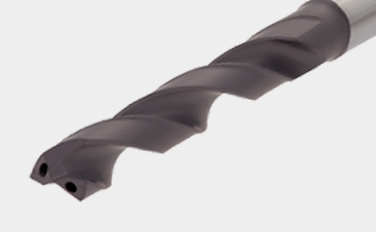
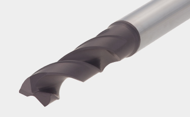
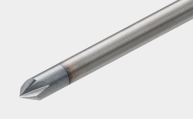
Broca de metal duro con recubrimiento para una estabilidad excelente
Combinación ideal de geometría de broca y composición del metal duro para un rendimiento excepcional en una amplia gama de aplicaciones de taladrado

Aplicaciones y características
Aplicaciones
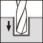
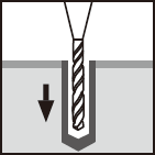

Características para DSW
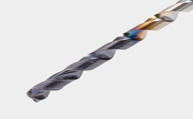
1. Nueva calidad de recubrimiento con mayor resistencia al desgaste
• Nueva calidad de metal duro con recubrimiento de gran versatilidad. Calidad perfecta para una durabilidad estable y prolongada de la herramienta en una amplia gama de materiales.
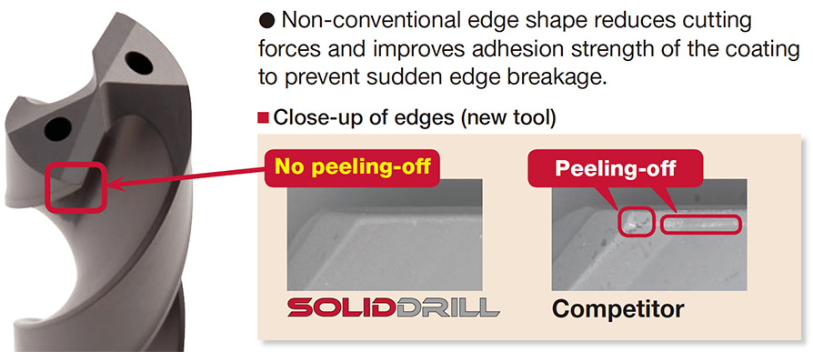
2. Su innovadora arista de corte ofrece un taladrado fiable
• La forma no convencional de la arista reduce las fuerzas de corte y mejora la fuerza de adherencia del recubrimiento para evitar la rotura repentina de la arista.
3. Estilo de mango estándar en todo el mundo – Estandarizado con DIN6535-Forma HA
• Sólo 6 diámetros de mango disponibles: ø6, ø8, ø10, ø12, ø14, ø16 mm. Esto reduce el número de mordazas necesarias.
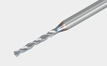
Características para DSM
1. Variedad de medidas y L/D
• Permite realizar agujeros profundos de hasta 5 a 15 veces el diámetro de la broca.
• Disponibles como artículos estándar de ø0,1 a ø3,0 mm en incrementos de 0,01 mm. Los diámetros de mango están unificados a ø3 mm.
2. Brocas de centrado para el mecanizado del agujero guía
- El tipo DSM-CP140 tiene un ángulo de punta de 140° que puede evitar eficazmente que la arista de corte se astille.
- El tipo DSM-CP90, que tiene un ángulo de punta de 90°, también puede utilizarse para chaflanar la boca del agujero.
Brocas y calidades
Brocas
DSW-DI (ø3 – ø12 mm)
- Con suministro de interior de refrigerante
DSW-DE (ø3 – ø12 mm)
- Sin refrigeración interior. Más económicas
DSW-CI (ø3 – ø10 mm)
- Cylindrical shank, with coolant holes
DSM (ø0.1 – ø3 mm)
- Broca de metal duro de diámetro pequeño, L/D (ULDR) = 5 – 15
DSM-CP (ø3 mm)
- Brocas para agujero previo
Calidades principales
AH725
![]()
![]()
![]()
![]()
- P15 – P30 / M15 – M30 / K25 – K30 / S15 – S25
- Buen equilibrio entre la resistencia al desgaste y al astillado
- Adecuada para el mecanizado de acero y acero inoxidable en condiciones de corte estándar
YH170
![]()
![]()
- P20 – P35 / M20 – M35
- Alta resistencia al desgaste y a la rotura
- Diseñada para el taladrado de acero al carbono y acero inoxidable
YH180
![]()
![]()
- Alta resistencia al desgaste
- Diseñado para el taladrado de acero al carbono y acero inoxidable
Ejemplos prácticos
Ejemplo #1
Ingeniería general
| Pieza: | Parte de máquina |
| Material: | C55 (ISO) |
| Broca: | DSW103-040-12DE3 |
| Diámetro de agujero: | øDc = 10.3 (mm) |
| Calidad: | AH725 |
| Condiciones de corte: | Vc = 50 (m/min) f = 0.3 (mm/rev) H = 24 (mm) Refrigeración: Taladrina (Exterior) Máquina: Horizontal MC |

Condiciones de corte estándar
DSW-DE (External supply)
| ISO | Workpiece material | Brinell hardness (HB) |
Cutting speedVc (m/min) | Feed: f (mm/rev) | ||||
|---|---|---|---|---|---|---|---|---|
| ø3 – ø6 | ø6 – ø10 | ø10 – ø16 | ø3 – ø6 | ø6 – ø10 | ø10 – ø12 | |||
 |
Low carbon steels (C < 0.3) SS400, SM490, S25C, etc. C15E4, E275A, E355D, etc. |
– 180 | 40 – 100 | 60 – 120 | 60 – 130 | 0.15 – 0.3 | 0.15 – 0.35 | 0.2 – 0.5 |
| Carbon steels (C > 0.3) S45C, S55C, , etc. C45, C55, etc. |
180 – 300 | 40 – 90 | 50 – 120 | 60 – 130 | 0.15 – 0.3 | 0.15 – 0.35 | 0.2 – 0.4 | |
| High alloy steels SCM440, etc. 42CrMo4, etc. |
250 – 350 | 40 – 80 | 50 – 100 | 50 – 100 | 0.1 – 0.2 | 0.15 – 0.3 | 0.15 – 0.35 | |
 |
Stainless steels SUS304, etc. X5CrNi18-9, etc. |
– 200 | 20 – 40 | 30 – 50 | 30 – 60 | 0.05 – 0.2 | 0.1 – 0.25 | 0.1 – 0.3 |
 |
Grey cast irons FC300, etc. 250, etc. |
– 200 | 40 – 90 | 50 – 95 | 50 – 100 | 0.15 – 0.3 | 0.2 – 0.4 | 0.2 – 0.5 |
| Ductile cast irons FCD450, etc. 450-10S, etc. |
– 300 | 30 – 80 | 40 – 90 | 45 – 90 | 0.1 – 0.3 | 0.2 – 0.4 | 0.2 – 0.4 | |
 |
Aluminium alloys ADC12, etc. AlSi11Cu3, etc. |
– | 40 – 90 | 50 – 100 | 50 – 100 | 0.15 – 0.3 | 0.2 – 0.4 | 0.2 – 0.5 |
 |
Titanium alloys Ti-6Al-4V, etc. |
– | 20 – 40 | 20 – 40 | 20 – 40 | 0.1 – 0.2 | 0.15 – 0.25 | 0.15 – 0.4 |
| Heat-resistant alloys, Inconel Inconel 718, etc. |
250 – | 10 – 30 | 10 – 30 | 10 – 30 | 0.03 – 0.07 | 0.05 – 0.1 | 0.07 – 0.12 | |
 |
High hardened steels SKD11, etc. X153CrMoV12, etc. |
– 40HRC | 20 – 40 | 20 – 40 | 20 – 40 | 0.05 – 0.15 | 0.05 – 0.15 | 0.05 – 0.2 |
- The cutting parameters shown in the table are merely a starting guideline for general machining. Values should be varied depending on the power or rigidity of the machine to be used. Optimum conditions should be selected depending on the actual chip control or damage on edges.
- When using the smaller diameter tools in each range, set the feed “f” to the lower recommended values.
- The coolant supply is critical for the provision of stable machining conditions and enhanced tool life. A large coolant volume should be supplied, especially when drilling di! cult-to-cut materials.
- When drilling stainless steel with low machinability such as austenitic stainless steel with a depth deeper than L/D = 3, a pecking cycle or internal coolant supply is recommended.
DSW-DI (Internal supply)
| ISO | Workpiece material | Brinell hardness (HB) |
Cutting speedVc (m/min) | Feed: f (mm/rev) | ||||
|---|---|---|---|---|---|---|---|---|
| ø3 – ø6 | ø6 – ø10 | ø10 – ø16 | ø3 – ø6 | ø6 – ø10 | ø10 – ø12 | |||
|
Low carbon steels (C < 0.3) SS400, SM490, S25C, etc. C15E4, E275A, E355D, etc. |
– 180 | 70 – 140 | 80 – 160 | 90 – 190 | 0.15 – 0.3 | 0.15 – 0.35 | 0.2 – 0.5 |
| Carbon steels (C > 0.3) S45C, S55C, , etc. C45, C55, etc. |
180 – 300 | 50 – 130 | 70 – 160 | 80 – 170 | 0.15 – 0.3 | 0.15 – 0.35 | 0.2 – 0.4 | |
| High alloy steels SCM440, etc. 42CrMo4, etc. |
250 – 350 | 40 – 100 | 60 – 140 | 60 – 160 | 0.1 – 0.2 | 0.15 – 0.3 | 0.15 – 0.35 | |
|
Stainless steels SUS304, etc. X5CrNi18-9, etc. |
– 200 | 25 – 75 | 50 – 100 | 50 – 120 | 0.05 – 0.2 | 0.1 – 0.25 | 0.1 – 0.3 |
|
Grey cast irons FC300, etc. 250, etc. |
– 200 | 80 – 140 | 100 – 160 | 100 – 180 | 0.15 – 0.3 | 0.2 – 0.4 | 0.2 – 0.45 |
| Ductile cast irons FCD450, etc. 450-10S, etc. |
– 300 | 70 – 140 | 80 – 150 | 80 – 170 | 0.1 – 0.3 | 0.2 – 0.4 | 0.2 – 0.45 | |
|
Aluminium alloys ADC12, etc. AlSi11Cu3, etc. |
– | 60 – 200 | 60 – 200 | 60 – 200 | 0.15 – 0.3 | 0.2 – 0.4 | 0.2 – 0.5 |
|
Titanium alloys Ti-6Al-4V, etc. |
– | 20 – 60 | 30 – 80 | 30 – 80 | 0.1 – 0.2 | 0.1 – 0.25 | 0.15 – 0.4 |
| Heat-resistant alloys, Inconel Inconel 718, etc. |
250 – | 10 – 30 | 10 – 40 | 10 – 40 | 0.03 – 0.07 | 0.05 – 0.1 | 0.07 – 0.15 | |
|
High hardened steels SKD11, etc. X153CrMoV12, etc. |
– 40HRC | 20 – 50 | 30 – 60 | 30 – 60 | 0.05 – 0.15 | 0.05 – 0.15 | 0.05 – 0.2 |
- The cutting parameters shown in the table are merely a starting guideline for general machining. Values should be varied depending on the power or rigidity of the machine to be used. Optimum conditions should be selected depending on the actual chip control or damage on edges.
- When using the smaller diameter tools in each range, set the feed “f” to the lower recommended values.
- Oil holes that become blocked may cause drill breakages. A fi lter to prevent the circulation of chips must be used on the coolant supply system.
DSW-CI (16xD, 20xD)
| ISO | Workpiece material | Cutting speed Vc (m/min) |
Feed: f (mm/rev) | ||
|---|---|---|---|---|---|
| Tool diameter: DC (mm) | |||||
| ø3 – ø5 | ø5.1 – ø8 | ø8.1 – ø10 | |||
|
Low carbon steels (C < 0.3) SS400, SM490, S25C, etc. C15E4, E275A, E355D, etc. |
70 – 90 | 0.1 – 0.18 | 0.1 – 0.2 | 0.1 – 0.25 |
| High carbon steels (C > 0.3) S45C, S55C, etc. C45, C55, etc. |
70 – 90 | 0.1 – 0.18 | 0.1 – 0.2 | 0.1 – 0.25 | |
| Low alloy steels SCM415, etc. 18CrMo4, etc. |
70 – 90 | 0.1 – 0.18 | 0.1 – 0.2 | 0.1 – 0.25 | |
| Alloy steels SCM440, SCr420, etc. 42CrMo4, 20Cr4, etc. |
75 – 85 | 0.08 – 0.14 | 0.08 – 0.18 | 0.12 – 0.2 | |
|
Stainless steels SUS304, SUS316, etc. X5CrNi18-9, X5CrNiMo17-12-2, etc. |
55 – 65 | 0.04 – 0.12 | 0.08 – 0.16 | 0.1 – 0.18 |
|
Grey cast irons FC250, etc. GG25, etc. |
80 – 100 | 0.14 – 0.24 | 0.16 – 0.26 | 0.18 – 0.3 |
| Ductile cast irons FCD700, etc. GGG70, etc. |
80 – 100 | 0.14 – 0.24 | 0.16 – 0.26 | 0.18 – 0.3 | |
|
Titanium alloys Ti-6Al-4V, etc. |
35 – 45 | 0.06 – 0.12 | 0.08 – 0.16 | 0.1 – 0.18 |
| Nickel-based alloys | 30 – 40 | 0.06 – 0.12 | 0.08 – 0.16 | 0.1 – 0.18 | |
DSW-CI (30xD)
| ISO | Workpiece material | Cutting speed Vc (m/min) |
Feed: f (mm/rev) | ||
|---|---|---|---|---|---|
| Tool diameter: DC (mm) | |||||
| ø3 – ø5 | ø5.1 – ø8 | ø8.1 – ø10 | |||
|
Low carbon steels (C < 0.3) SS400, SM490, S25C, etc. C15E4, E275A, E355D, etc. |
70 – 90 | 0.08 – 0.11 | 0.12 – 0.17 | 0.1 – 0.22 |
| High carbon steels (C > 0.3) S45C, S55C, etc. C45, C55, etc. |
70 – 90 | 0.08 – 0.11 | 0.12 – 0.17 | 0.1 – 0.22 | |
| Low alloy steels SCM415, etc. 18CrMo4, etc. |
70 – 90 | 0.08 – 0.11 | 0.12 – 0.17 | 0.1 – 0.22 | |
| Alloy steels SCM440, SCr420, etc. 42CrMo4, 20Cr4, etc. |
75 – 85 | 0.06 – 0.09 | 0.08 – 0.14 | 0.1 – 0.18 | |
|
Stainless steels SUS304, SUS316, etc. X5CrNi18-9, X5CrNiMo17-12-2, etc. |
55 – 65 | 0.04 – 0.1 | 0.08 – 0.14 | 0.1 – 0.16 |
|
Grey cast irons FC250, etc. GG25, etc. |
80 – 100 | 0.14 – 0.22 | 0.16 – 0.26 | 0.18 – 0.25 |
| Ductile cast irons FCD700, etc. GGG70, etc. |
80 – 100 | 0.14 – 0.22 | 0.16 – 0.24 | 0.18 – 0.25 | |
|
Titanium alloys Ti-6Al-4V, etc. |
35 – 45 | 0.06 – 0.1 | 0.08 – 0.12 | 0.1 – 0.13 |
| Nickel-based alloys | 30 – 40 | 0.06 – 0.1 | 0.08 – 0.12 | 0.08 – 0.13 | |
DSM
| ISO | Workpiece material | Hardness | Cutting speedVc (m/min) | Feed: f (mm/rev) | ||||||
|---|---|---|---|---|---|---|---|---|---|---|
| ø0.1 – ø0.3 | ø0.31 – ø0.5 | ø0.51 – ø3 | ø0.1 – ø0.3 | ø0.31 – ø0.5 | ø0.51 – ø1 | ø1.01 – ø2 | ø2.01 – ø3 | |||
|
Carbon steels, Alloy steels |
– 300HB | 5 – 20 | 15 – 30 | 25 – 60 | 0.001 – 0.004 | 0.002 – 0.01 | 0.005 – 0.05 | 0.03 – 0.09 | 0.05 – 0.1 |
|
Stainless steels | – 200HB | 2 – 12 | 6 – 18 | 10 – 20 | 0.0005 – 0.004 | 0.002 – 0.008 | 0.005 – 0.03 | 0.01 – 0.04 | 0.02 – 0.05 |
|
Grey cast irons | 150 – 250HB | 5 – 15 | 10 – 25 | 20 – 50 | 0.0005 – 0.004 | 0.002 – 0.012 | 0.005 – 0.03 | 0.01 – 0.06 | 0.03 – 0.12 |
| Ductile cast irons | 150 – 250HB | 5 – 15 | 10 – 25 | 20 – 50 | 0.001 – 0.003 | 0.002 – 0.01 | 0.005 – 0.02 | 0.01 – 0.05 | 0.03 – 0.1 | |
|
Aluminium alloys | – | 10 – 20 | 10 – 30 | 20 – 50 | 0.001 – 0.01 | 0.005 – 0.03 | 0.01 – 0.05 | 0.04 – 0.15 | 0.06 – 0.2 |
| Copper / Brass | – | 10 – 20 | 10 – 30 | 20 – 50 | 0.001 – 0.01 | 0.005 – 0.03 | 0.01 – 0.05 | 0.04 – 0.15 | 0.06 – 0.2 | |
|
Heat-resistant alloys | – 40HRC | 2 – 6 | 5 – 10 | 8 – 20 | 0.0005 – 0.003 | 0.002 – 0.004 | 0.002 – 0.004 | 0.002 – 0.004 | ※ |
|
High hardened steels | – 50HRC | 4 – 8 | 6 – 10 | 6 – 16 | 0.0005 – 0.002 | 0.001 – 0.005 | 0.005 – 0.02 | 0.01 – 0.03 | 0.02 – 0.06 |
※ Not recommended
- When the drilling depth is deeper than L/D = 5, use drill pecking every 10 to 50% of the drill diameter.
- The above cutting conditions are applied to when a water soluble cutting fluid is used. For drilling a hole smaller than ø0. 3 mm, use of a starting drill is recommended.
- When setting the drill, the drill runout should be within 0.002 mm on the taper. (Especially for the drill diameter smaller than ø0.5 mm)
DSM-CP
| ISO | Workpiece material | Hardness | Cutting speedVc (m/min) | Feed: f (mm/rev) | |
|---|---|---|---|---|---|
| DSM-CP90 | DSM-CP140 | ||||
|
Carbon, Mild and Alloy steels | – 300HB | 30 – 80 | 0.01 – 0.06 | 0.03 – 0.08 |
|
Stainless steels | – 200HB | 15 – 40 | 0.01 – 0.03 | 0.02 – 0.06 |
|
Grey and ductile cast irons | 150 – 250HB | 30 – 80 | 0.02 – 0.06 | 0.05 – 0.1 |
|
Aluminium alloys | – | 60 – 120 | 0.02 – 0.1 | 0.05 – 0.15 |
|
High hardened steels | – 45HRC | 10 – 40 | ※ | 0.01 – 0.05 |
※ Not recommended
- Use DSM-CP140 for drilling hard materials and stainless steel that have work-hardening characteristic.
- The above cutting conditions are designed when using water-soluble cutting fluid, in which case, set the cutting speed to the lower side of the range.
Para obtener más información sobre este producto, visite nuestro catálogo en línea o descargue el informe del producto:
e-Catalog
SolidDrill (Métrico)
GigaMiniDrill (Métrico)


Industrias |
|
Industrias Más información |

e-Catalog |
|
Catalogo
Electronico Más información |
Recursos
 Tungaloy APP
 TUNG NaviRecomendaciones de herramientas según necesidades específicas
 Machine Power Calculator
 Turning Insert Selection Guide
 Informes de Éxito de TungaloyExplore la plataform TSR de Tungaloy para obtener información sobre casos específicos de mecanizado con una búsqueda sencilla.
 Guías técnicasAcceda a las guías técnicas de Tungaloy para obtener información valiosa, referencias y recursos.
 MatrixSistema de almacenamiento de stock
 Special tool drawing generatorQuickly generate simple drawings for special products.