
Chapter 1
High-feed milling is a roughing strategy that increases productivity by using very high feed per tooth with a shallow axial depth of cut. The key idea is simple: keep the chip thin, redirect the cutting force more axially, and use feed rate as the main productivity lever.
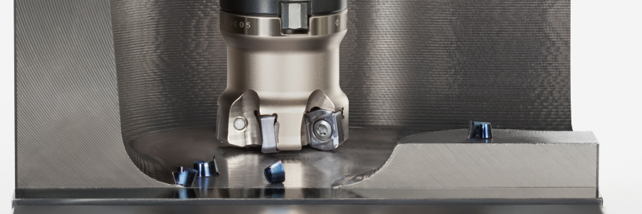
In milling, productivity is usually improved by changing one of three parameters: cutting speed, feed per tooth, or depth of cut. Increasing cutting speed can shorten tool life due to heat. Increasing depth of cut can overload the insert and machine. High-feed milling takes a different route: it increases feed per tooth while keeping chip thickness under control.

Can improve cycle time, but often increases heat and tool wear.
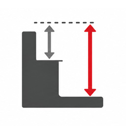
Raises material removal per pass, but increases load and power demand.

The high-feed approach: raise feed while controlling chip thickness.
A common misunderstanding is to assume that feed per tooth and chip thickness are the same. In a 90° shoulder cutter, that is nearly true. In high-feed milling, however, the small entering angle makes the actual chip much thinner than the programmed feed per tooth.
High-feed cutters use a small entering angle, typically below 30°. This creates the chip thinning effect. The smaller the entering angle, the thinner the chip becomes for the same feed per tooth.
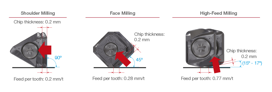
A simplified way to understand the relationship is:
This explains why a high-feed cutter can run at a much higher feed per tooth. At a small entering angle, only part of the programmed feed becomes actual chip thickness.
| Entering angle | Chip thickness ratio | What it means |
|---|---|---|
| 90° shoulder milling | ≈ 100% | Chip thickness is close to feed per tooth |
| 45° face milling | ≈ 70% | Some chip thinning occurs |
| 15° high-feed milling | ≈ 26% | Much higher feed can be used while keeping chips thin |
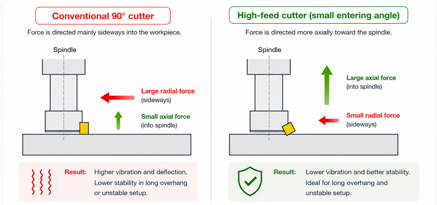
The small entering angle changes the direction of the cutting force. Instead of pushing strongly sideways into the workpiece, more of the force is directed axially toward the spindle. This helps reduce vibration, especially in long overhang or unstable setups.
| Main purpose | High-productivity roughing |
| Typical strategy | High feed per tooth + shallow axial depth of cut |
| Typical entering angle | Below 30°, often around 10°–20° depending on cutter design |
| Main advantage | High table feed with controlled chip thickness |
| Main limitation | Not suitable for deep axial cutting or finishing walls |
Chapter 2
High-feed milling is powerful, but it is not magic. It delivers strong advantages when the application fits the method, and it has clear limitations when the operation requires deep cuts, finishing accuracy, or unsupported workpiece conditions.

Feed per tooth can be increased significantly while chip thickness remains controlled.

More axial force direction helps reduce radial vibration and chatter.

Thinner chips reduce impact on the edge and can help reduce chipping.
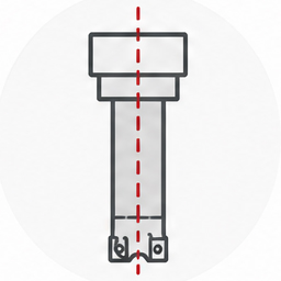
Stable force direction makes HFM useful when tool projection is long.
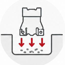
Excellent for cavities, pockets, face milling, and general material removal.
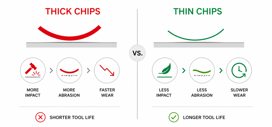
Insert damage is often driven by impact and abrasion. Thick chips increase impact on the cutting edge, while repeated rubbing contributes to wear. High-feed milling reduces effective chip thickness, helping to control both mechanisms.
| Limitation | Why it matters | How to manage it |
|---|---|---|
| Shallow ap | HFM is designed for shallow axial depth of cut, not deep axial engagement. | Use multiple passes and keep the process within the intended APMX range. |
| Not a finishing tool | The high-feed geometry is optimized for roughing, not final wall or floor finish. | Leave finishing allowance and use a finishing cutter afterwards. |
| Machine feed capability | Very high table feed requires enough acceleration and control response. | Check machine limitations, especially in small pockets and short tool paths. |
| Programming sensitivity | Actual engagement can change quickly in corners, arcs, or helical paths. | Use smooth tool paths and reduce feed when engagement increases. |
| Weak workpieces | Axial force can deform thin or weakly supported parts. | Evaluate the strong and weak side of the workpiece before applying HFM. |
Chapter 3
High-feed milling can be used in many industries, but the best results come when the operation matches the strengths of the method: high feed, shallow depth, stable engagement, and efficient roughing.
Fast roughing of cavities and deep pockets using multiple shallow passes.

Efficient roughing of titanium, HRSA, and structural components where stability matters.

Flexible roughing strategy for different component shapes and batch sizes.
Stable roughing of large components where process security is important.

High-efficiency machining for mass-produced steel and stainless-steel components, reducing machining time.
| Operation | Why HFM works | Main caution |
|---|---|---|
| Pocket machining | High feed enables fast cavity roughing with thin chips. | Chip evacuation and corner engagement must be controlled. |
| Face milling | Large surfaces can be machined quickly with stable cutting load. | Choose cutter size and pitch according to machine rigidity. |
| Ramping and helical entry | Controlled entry reduces shock compared with direct plunging. | Check actual cutting engagement and tool capability. |
| Slotting | Can be effective when stability and chip evacuation are controlled. | Full engagement increases load and chip evacuation risk. |
| Long overhang roughing | Axial force direction reduces vibration tendency. | Overhang ratio and insert geometry remain critical. |
| Material | Main Focus | General Approach |
|---|---|---|
| Steel / Cast Iron | Productivity | Use the most productive cutter concept within stable engagement limits. |
| Stainless Steel | Stability and edge security | Prefer stable insert styles and controlled cutting conditions. |
| Titanium / HRSA | Heat, edge load, and stability | Control engagement carefully and prioritize process security. |
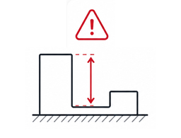
Use a shoulder cutter when axial depth and wall generation are the main requirements.

HFM is a roughing method; finishing should normally be done with a dedicated finishing tool.
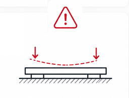
Check the force direction carefully when the workpiece is thin or weakly clamped.
Chapter 4
This chapter focuses on practical details that affect real machining results: effective diameter, programmed radius, long overhang behavior, weak workpieces, APMX, and tool path strategy.
In high-feed milling, the effective cutting diameter (DC) is usually smaller than the tool diameter (DCX). This matters when calculating cutting speed, engagement, and actual tool path. Do not assume the nominal cutter diameter alone represents the actual cutting diameter.
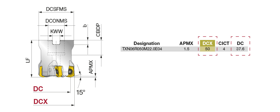
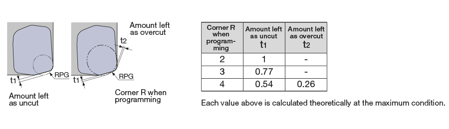
The programmed radius and the actual machined profile can differ because of insert shape and cutter geometry. This is especially important when using high-feed tools near walls, shoulders, or remaining stock.
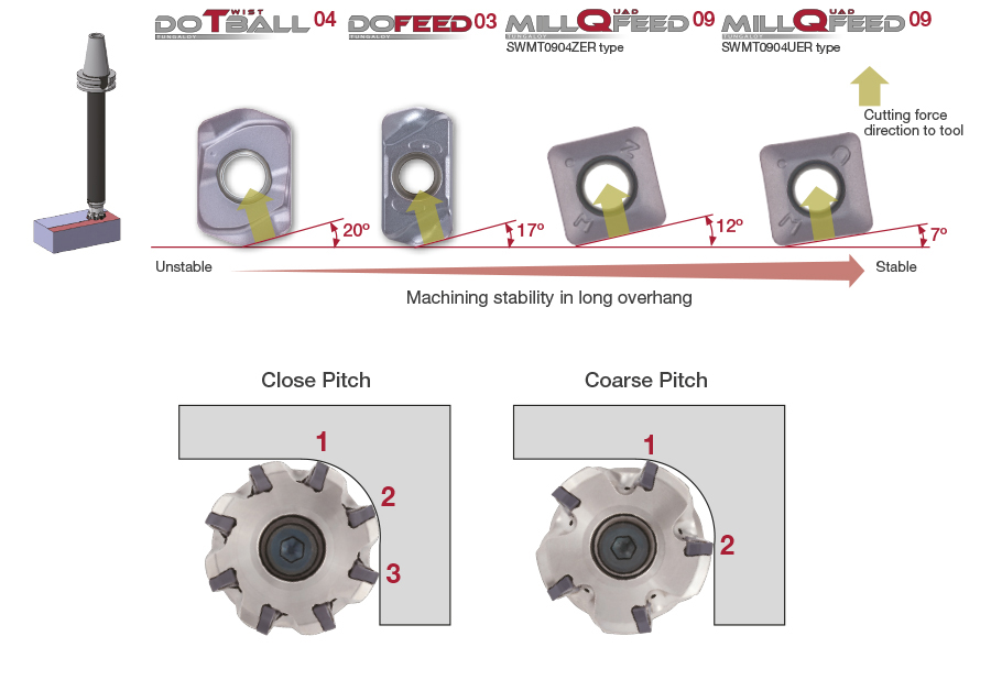
Long overhang increases vibration risk. High-feed milling can help because the main force direction is more axial, but cutter diameter, entering angle, shank rigidity, and insert geometry still determine the maximum stable overhang.
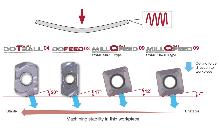
The direction of the cutting force must be considered carefully. If the bottom side or support side of the workpiece is weak, high-feed milling may deform the part. In those cases, another cutter style or a modified cutting strategy may be more suitable.
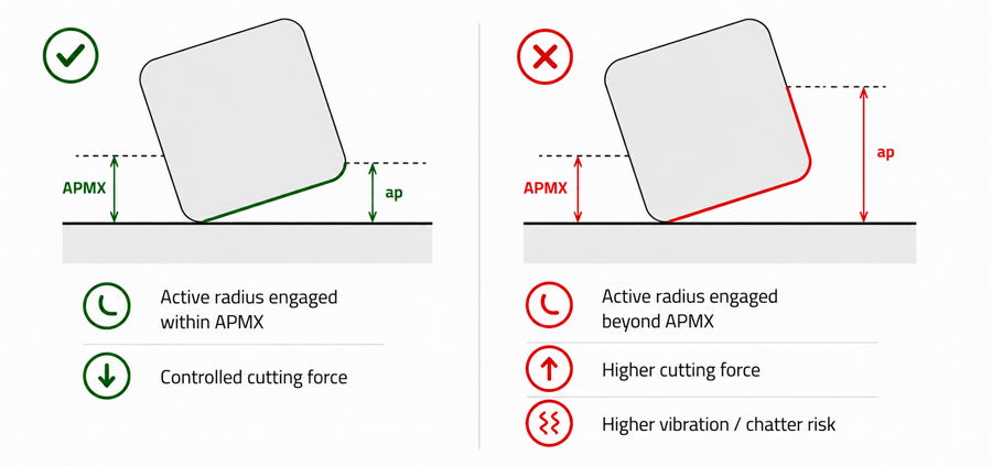
High-feed tools are designed for a specific shallow axial depth of cut. Running beyond the intended cutting zone can increase chatter and load because more of the insert radius becomes engaged. For best performance, stay within the recommended APMX and maintain controlled engagement.
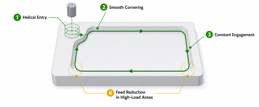
High feed values are powerful, but actual engagement changes during pocketing, helical entry, corners, and arcs. Smooth tool paths, controlled radial engagement, and feed reduction in high-load sections help keep the process stable.
Chapter 5
When high-feed milling does not perform as expected, the cause is often related to force direction, chip thickness, engagement, overhang, or machine capability rather than the cutter alone.
| Problem | Likely Cause | Recommended Action |
|---|---|---|
| Chatter in long overhang | Overhang too long, insufficient rigidity, or unsuitable geometry | Reduce overhang, choose a more stable insert style, lower ap, or reduce feed. |
| Insert chipping | Chip too thick, entry shock, or sudden engagement increase | Reduce effective chip load, improve entry, and smooth tool path transitions. |
| Short tool life | Excessive impact, heat, or rubbing | Check chip thickness, cutting speed, grade, coolant, and engagement stability. |
| Poor surface finish | Feed too high for finish requirement or unstable setup | Use HFM for roughing, leave allowance, and finish with an appropriate finishing cutter. |
| Machine cannot reach feed rate | Acceleration limit, short tool path, or CNC feed control limitation | Check actual feed, use smoother paths, and adjust cutting conditions to machine capability. |
| Part deformation | Workpiece is thin or unsupported in the axial force direction | Improve support, reduce cutting load, or use another milling strategy. |
Once the basic principles, limitations, and application conditions are clear, use the Quick Selection Guide to find the most suitable Tungaloy high-feed milling solution for your case.